Advertisement
Table of Contents
- 1 Job Specification Sheet
- 2 General Residential Installation Check List
- 3 Valve Installation and Start-Up Procedures
- 4 Control Start-Up Procedures
- 5 Set Time of Day
- 6 Final Setup
- 7 Control Operation
- 8 Control Valve Assembly
- 9 By-Pass Valve Assembly, Plastic
- 10 By-Pass Valve Assembly, Brass
- 11 2300 Safety Brine Valve
- 12 Service Assemblies
- Download this manual
Advertisement
Table of Contents

Subscribe to Our Youtube Channel
Related Manuals for Fleck 5600SE


Summary of Contents for Fleck 5600SE
- Page 1 MODEL 5600SE Downflow Brining Service Manual...
-
Page 2: Job Specification Sheet
MODEL 5600SE Downflow Job Specification Sheet Job Number ___________________________________ Model Number ________________________________ Water Test ____________________________________ Capacity Of Unit ________________________ Max. _____________ Per Regeneration Mineral Tank Size: Diameter ___________________ Height _____________________ Under Bedding ____________________________ Amount _______________________ Type Of Media ____________________________ Cubic Feet _____________________... -
Page 3: General Residential Installation Check List
MODEL 5600SE Downflow General Residential Installation Check List WATER PRESSURE: A minimum of 25 pounds of water pressure is required for regeneration valve to operate effectively. ELECTRICAL FACILITIES: An uninterrupted alternating current (A/C) supply is required. Please make sure your voltage supply is compatible with your unit before installation. -
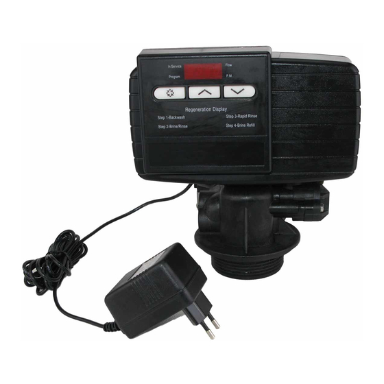
Page 4: Control Start-Up Procedures
MODEL 5600SE Downflow Control Start-Up Procedures Set Time Of Day Service Indicator: Flow Indicator: Service Valve In Service - Dot On 12:00 Flow Flashing Dot With Water Flow Extra Cycle Tonight - Flashing Dot P.M. Indicator Program P.M. Set Up Button... - Page 5 MODEL 5600SE Downflow Control Start-Up Procedures, Continued Depending on current control programming, option setting displays that are not required to be set will not be viewed. Set Control Programming Service Flow Program Mode Indicator: Program P.M. Program Mode Entered - Dot On...
- Page 6 MODEL 5600SE Downflow Control Start-Up Procedures, Continued Set Control Programming Service 8 :0 0 Flow Program P.M. Extra Cycle Button Regeneration Display Step 1 - Backwash Step 3 - Rapid Rinse Step 2 - Brine / Rinse Step 4 - Brine Refill When starting an Extra Cycle, you will have one or two options: 1.
-
Page 7: Final Setup
MODEL 5600SE Downflow Control Start-Up Procedures, Continued Fast Cycle Valve Thru Regeneration Service 1 - - 8 Flow Program P.M. Extra Cycle Button Regeneration Display Step 1 - Backwash Step 3 - Rapid Rinse Step 2 - Brine / Rinse Step 4 - Brine Refill A. -
Page 8: Control Operation
MODEL 5600SE Downflow Control Operation Timeclock Regeneration Valves In normal operation the Time Of Day Display will be viewed at all times. The control will operate normally until the number of days since the last regeneration reaches the Regeneration Day Override setting. Once this occurs, a regeneration cycle will then be initiated at the preset Regeneration Time. - Page 9 MODEL 5600SE Downflow Water Conditioner Flow Diagrams (downflow brining) Using Black Cycle Cam (P/N 17438) Service Position Backwash Position (Regeneration Cycle Step #1) Page 9...
- Page 10 MODEL 5600SE Downflow Water Conditioner Flow Diagrams (downflow brining) Using Black Cycle Cam (P/N 17438), Continued Brine/Slow Rinse Position (Regeneration Cycle Step #2) Rapid Rinse Position (Regeneration Cycle Step #3) Page 10...
- Page 11 MODEL 5600SE Downflow Water Conditioner Flow Diagrams (downflow brining) Using Black Cycle Cam (P/N 17438), Continued Brine Tank Fill Position (Regeneration Cycle Step #4) Service Position Page 11...
-
Page 12: Control Valve Assembly
MODEL 5600SE Downflow Control Valve Assembly Page 12... - Page 13 MODEL 5600SE Downflow Control Valve Assembly Part List Item No. Quantity Part No. Description 13255 Adapter Clip 13242 Seal ..61400-12 Valve Body Assembly - 1” dist..61400-11 Valve Body Assembly - 13/ ” Dist. 13304 “O” Ring - Distributor Tube - 1”...
- Page 14 MODEL 5600SE Downflow Valve Powerhead Assembly Page 14...
- Page 15 MODEL 5600SE Downflow Valve Powerhead Assembly, Continued Item No. Quantity Part No. Description 26001-02 Drive Housing, Black 12473 Screw, Drive Mount 19474 Wire Harness, Power 13299 Spring Washer 13017 Idler Gear 19080 Spring, Detent 13300 Ball, Detent 25005 Main Drive Gear & Shaft (Downflow Brining - Black)
- Page 16 MODEL 5600SE Downflow 3/4” Turbine Meter Assembly Parts List Item No. Quantity Part No. Description 13314 Screw, Hex Washer, 8-18 x 5/8 19569 Clip, Flow Meter 19797 Meter Body Assembly, 3/4” Turbine 13305 O Ring, -119 19791-01 Harness Assembly, Flow Meter...
-
Page 17: By-Pass Valve Assembly, Plastic
MODEL 5600SE Downflow By-Pass Valve Assembly, Plastic Parts List Item No. Quantity Part No. Description 19723 By-Pass Valve Body, Plastic 11183 O Ring, -015 19724 Cap, By-Pass 17512 Screw, Hex Washer Head, #6-24 x 3 17820 Plug, By-Pass 18661 O Ring, -218... -
Page 18: By-Pass Valve Assembly, Brass
MODEL 5600SE Downflow By-Pass Valve Assembly, Brass Parts List Item No. Quantity Part No. Description 17290 By-Pass Valve Body, 3/4" 17290NP By-Pass Valve Body, 3/4" Nickel Plate 13399 By-Pass Valve Body, 1" 13399NP By-Pass Valve Body, 1", Nickel Plate 11726... -
Page 19: 2300 Safety Brine Valve
MODEL 5600SE Downflow 2300 Safety Brine Valve Parts List Item No. Quantity Part No. Description 60027-00 2300 Safety Brine Valve Body 10138 Ball, 3/8" 11566 Bull Stop 10328 Elbow, 1/4 x 1/4 T 10332 Insert, 3/8 10330 Sleeve, 3/8 10329... - Page 20 MODEL 5600SE Downflow Valve Wiring Diagram BLACK HCAM RIBBED BLUE SMOOTH WHITE WHITE YELLOW CB1 - 5600SE Circuit Board VDM - Valve Drive Motor EM - Electronic Flow Meter (Optional) SW1 - Homing Switch SW2 - Step Switch HCAM -...
- Page 21 Model 5600SE Downflow Service Instructions A. TO REPLACE BRINE VALVE, INJECTORS, AND 4. Put new timer on top of valve. Be sure drive pin on SCREEN main gear engages slot in drive yoke. 1. Turn off water supply to conditioner: 5.
- Page 22 MODEL 5600SE Downflow Service Instructions, Continued 4. Pull upward on end of piston rod yoke until assembly is out of valve. Remove and replace seals and spac- ers. 5. Take piston assembly and push piston into valve by means of the end plug. Twist yoke carefully in a clockwise direction to properly align it with drive gear.
- Page 23 MODEL 5600SE Downflow Service Instructions, Continued PROBLEM CAUSE CORRECTION Softener Fails To Electrical Service To Unit Has Assure Permanent Electrical Regenerate. Been Interrupted. Service (Check Fuse, Plug, Pull Chain or Switch). Timer Is Not Operating Properly. Replace Timer. Defective Valve Drive Motor.
- Page 24 MODEL 5600SE Downflow Service Instructions, Continued PROBLEM CAUSE CORRECTION Iron In Conditioned W ater. Fouled Resin Bed. Check Backwash, Brine Draw And Brine Tank Fill, Increase Frequency Of Regeneration. Increase Backwash Time. Iron Content Exceeds Add Iron Removal from Recommended Parameters...
-
Page 25: Service Assemblies
60022-50 BLFC .50 GPM For Illustration, See Page 14 60022-100 BLFC 1.0 GPM For Illustration, See Page 12 60756-0211 ..5600SE Metered Powerhead Assembly 17307 Flow Washer .125 GPM Black, Backwash First Label, DF 12094 Flow Washer .25 GPM For Illustration, See Page 14 12095 Flow Washer .50 GPM... - Page 26 P/N 19742 11/97 Not Released For Printing...
Need help?
Do you have a question about the 5600SE and is the answer not in the manual?
Questions and answers
What kind (or size) of salt pellets should I use with the Model 5600se Downflow water softener?