
Subscribe to Our Youtube Channel
Related Manuals for Fleck 2750


Summary of Contents for Fleck 2750
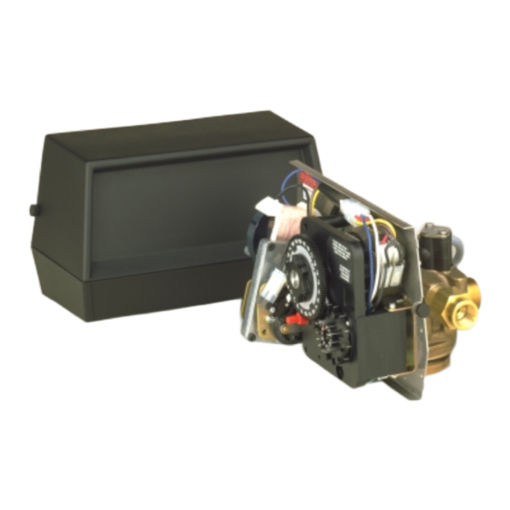
- Page 1 MODEL 2750 DOWNFLOW CONTROL VALVE Service Manual IMPORTANT: Fill in pertinent information on page 2 for future reference.
-
Page 2: Job Specification Sheet
* MINERAL TANK SIZE DIA. ______ HEIGHT_________ * BRINE TANK SIZE & SALT SETTING PER REGENERATION: _________________________________________________________________ * 2750 CONTROL VALVE SPECIFICATIONS 1) Type of Timer (see pages 16,17, & 18) A) 7 day or 12 day B) *310 to 5,270 gallon meter or... -
Page 3: General Commercial Pre-Installation Check List
MODEL 2750 DOWNFLOW General Commercial Pre-Installation Check List WATER PRESSURE: A minimum of 25 pounds of water pressure is required for regeneration valve to operate effectively. ELECTRICAL FACILITIES: A continuous 110 volt, 60 Hertz current supply is required. Make certain the current supply is always hot and cannot be turned off with another switch. - Page 4 MODEL 2750 DOWNFLOW Water Conditioners Flow Diagrams BRINE VALVE SERVICE POSITION FLOW CONTROL INLET MINERAL TANK BRINE TANK Hard water enters unit at valve inlet and flows down thru the mineral in the mineral tank. Conditioned water enters center tube thru the bottom distributor then flows up thru the...
- Page 5 MODEL 2750 DOWNFLOW Water Conditioners Flow Diagrams (Cont’d.) SLOW RINSE POSITION BRINE VALVE FLOW CONTROL INLET MINERAL TANK BRINE TANK Hard water enters unit at valve inlet flows up into injector housing and down thru nozzle ...
- Page 6 MODEL 2750 DOWNFLOW Control Drive Assembly (see opposite page for parts list) Page 6 Printed in U.S.A.
- Page 7 MODEL 2750 DOWNFLOW Control Drive Assembly Parts List Item No. Quantity Part No. Description 1 ..1 ..14884 ... . . Back Plate 1 .
- Page 8 MODEL 2750 DOWNFLOW Control Valve with 1700 Injector (see opposite page for parts list) Page 8 Printed in U.S.A.
- Page 9 MODEL 2750 DOWNFLOW Control Valve Parts List Item No. Quantity Part No. Description 1 ..1 ..14749 ... . . Valve Body 2 .
-
Page 10: 1600 Series Brine System Assembly
MODEL 2750 DOWNFLOW 1600 Series Brine System Assembly PARTS LIST Item No. Quantity Part No. Description 1 ... 1... . 10328....90° Elbow - 1/4″ Pipe Thd. to 3/8″ Tube 2 . - Page 11 MODEL 2750 1700 Series Brine System PARTS LIST Item No. Quantity Part No. Description 1..1 ..14792 ..End Plug 2..1 ..13201 ..O-Ring - End Plug 3.
- Page 12 MODEL 2750 DOWNFLOW Service Valve Operator 10 9 PARTS LIST Item No. Quantity Part No. Description 1 ... 1... . 11749....Guide, Brine Valve Stem 2 .
- Page 13 MODEL 2750 ECONOMINDER 1″ Meter Assembly PARTS LIST Item No. Quantity Part No. Description 1 ... 1 ... 14959 ....Meter Body 2 .
- Page 14 MODEL 2750 ECONOMINDER Timer Assembly (see opposite page for parts list) Page 14 Printed in U.S.A.
- Page 15 MODEL 2750 ECONOMINDER Timer Assembly Parts List Item No. Quantity Part No. Description 1 ... 1 ... 13708-01 ... . . Timer Housing Assembly 2 .
- Page 16 MODEL 2750 ECONOMINDER 1″ Commercial Demand Regeneration Control Timer Settings Typical Programming Procedure How To Manually Regenerate Your Water Conditioner At Any Time. Calculate the gallon capacity of the system, subtract the Turn the manual regeneration knob clockwise. necessary reserve requirement and set the appropriate...
-
Page 17: Timer Setting Procedure
MODEL 3200 TIMER Timer Setting Procedure How To Set Days On Which Water Conditioner Is To Regenerate: SERVICE Rotate the skipper wheel until the number “1” is at the red 24 HR. GEAR POSITION pointer. Set the days that regeneration is to occur by slid- MANUAL REGENERATION INDICATOR ing tabs on the skipper wheel outward to expose trip fin-... - Page 18 MODEL 3200 & 3210 Timer Series Regenerating Cycle Program Setting Procedure (Brine Tank Refill Separate from Rapid Rinse) How To Set The Regeneration Cycle Program: The regeneration cycle program on your water conditioner BRINE & RINSE PROGRAM SECTION has been factory preset, however, portions of the cycle or WHEEL FOR (2 MIN.
- Page 19 MODEL 2750 DOWNFLOW Flow Data & Injector Draw Rates Page 19 Printed in U.S.A.
- Page 20 2750 System #4 Valve Wiring Page 20 Printed in U.S.A.
- Page 21 2750 System #4 With Remote Meter Valve Wiring Page 21 Printed in U.S.A.
- Page 22 2750 System #5 Valve Wiring Page 22 Printed in U.S.A.
- Page 23 2750 System #6 Valve Wiring Page 23 Printed in U.S.A.
- Page 24 2750 24V/120V System #7 Valve Wiring Page 24 Printed in U.S.A.
- Page 25 2750 230V System #7 Valve Wiring Page 25 Printed in U.S.A.
- Page 26 MODEL 2750 DOWNFLOW Service Instructions PROBLEM CAUSE CORRECTION Softener fails to regenerate. A. Electrical service to unit has been A. Assure permanent electrical interrupted. service (check fuse, plug, pull chain or switch). B. Timer is defective. B. Replace timer. C. Reset time of day.
- Page 27 MODEL 2750 DOWNFLOW Service Instructions (Cont’d.) PROBLEM CAUSE CORRECTION Softener fails to draw brine A. Drain line flow control is plugged. A. Clean injector and replace screen. B. Clean injector. B. Injector is plugged. C. Clean screen. C. Injector screen plugged.
- Page 28 MODEL 2750 System #4 - Typical Single Tank Installation with Optional Meter MANUAL OPTIONAL SHUTOFF 2750 METER 3-WIRE SERVICE CORD DRAIN BRINE LINE RESIN TANK BRINE TANK Page 28 Printed in U.S.A.
- Page 29 MODEL 2750 System #5 Interlock - Typical Twin Tank Installation with Optional 2 Meter Interlock and No Hard Water Bypass DIAPHRAGM OPERATED VALVE MANUAL SHUTOFF VALVE ELECTRICAL INTERLOCK CORD PLUG DRAIN LINE UNIT 2 BRINE LINE PRESSURE SUPPLY S.V.O. RESIN...
- Page 30 MODEL 2750 System #6 - Twin Series Regeneration Installation with a Remote Meter MANUAL SHUTOFF VALVE METER DRAIN LINE ELECTRICAL INTERLOCK CORD PLUG DRAIN LINE UNIT 2 BRINE LINE RESIN TANK BRINE TANK 2 tanks, 1 meter, series regeneration system. Both units in service at the same time.
- Page 31 MODEL 2750 System #7 - Twin Alternator Installation With a Remote Meter METER MANUAL SHUTOFF VALVES 3-WIRE SERVICE CORD 4-WAY SOLENOID BRINE VALVE VALVE DRAIN RESIN BRINE TANK TANK ELECTRICAL INTERLOCK CORD (OPTIONAL) RESIN DIAPHRAGM TANK BRINE OPERATED TANK VALVE 2 tanks, 1 meter;...
-
Page 32: Service Assemblies
1 ..14785 ..Flow Control Retainer 1 ..14451 ..Piston, 2750 1 ..14790 ..Brine Valve Body 1 . - Page 33 MODEL 2750 Service Assemblies (Cont’d.) 60050-21 2750 Drive Assy., 120V 6071 0-XX BLFC, 1″ Specify Flow Rate Range 8.0 - 25.0 GPM 2 ..10218 ..Micro Switch 1 ..10250 ..Retaining Ring 60391 2750 Meter Assy., STD...
- Page 34 P/N 15512 Rev. 2 3/00 Printed XX/00...
Need help?
Do you have a question about the 2750 and is the answer not in the manual?
Questions and answers