Table of Contents
Advertisement
Advertisement
Table of Contents

Related Manuals for GCC Technologies AR-24


Summary of Contents for GCC Technologies AR-24
- Page 1 AR-24 User Manual http://www.GCCworld.com V.10 2018 Mar.
- Page 2 NOTICE GCC reserves the right to modify the information contained in this user manual at any time without prior notice; un-authorised modification, copying distribution or display is prohibited. All comments, queries or suggestions concerning this manual please consult with your local dealer. V.10 2018 Mar.
- Page 3 AR-24 user manual Important Information Thank you for purchasing the AR-24 Cutting Plotter. Before you use the cutting plotter, please make sure that you have read the safety precautions and instructions below. Caution SAFETY PRECAUTIONS! For safety concern, please always hold the cutter firmly from the bottom while moving it.
-
Page 4: Table Of Contents
2.6.2.3 Re-install Sure Cuts A Lot Software 2-31 3.Operation The Control Panel VLCD File Uploader Data Transmission AR-24 Print Driver setting 3.5.1 Option Page Reference Parameter setting for different materials 4. Basic Maintenance Cleaning the cutting Plotter Cleaning the Grid Drum Cleaning the Pinch Rollers... - Page 5 AR-24 user manual 5. Trouble Shooting What if AR-24 cannot Operate? Cutting Quality Problems Appendix AR-24 Specification Blade Specification CorelDraw Instruction Sure Cuts A Lot Table of Contents...
-
Page 6: General Information
AR-24 user manual Chapter 1 General Information Package Items The package of AR-24 contents the items listed below, please check carefully. If you find any item missing, please consult your local dealer for further assistance. Item Quantity Cutting Plotter 1 Set... -
Page 7: The Appearance
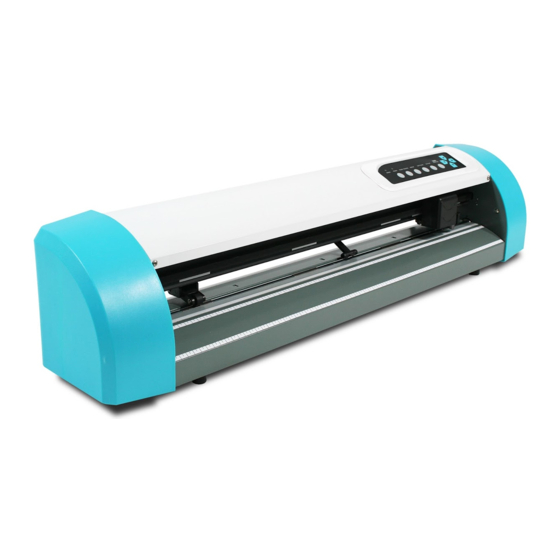
AR-24 user manual The Appearance (AR-24) 1.3.1 The Front View 【Figure 1-1】 Object Description Primary Pinch Roller To help hold the media during cutting. Slicing Groove To help slice off media. Alignment Ruler To align media with clear guideline marks Tool Carriage To help perform cutting job with installed blade or pen. - Page 8 AR-24 user manual 1.3.3 The Side Views 【Figure 1-3】 【Figure 1-4】 Object Description Serial Interface Connector To connect the machine with a computer through a RS-232 cable. USB Connector To connect the machine with a computer through a USB cable.
-
Page 9: Installation
AR-24 User Manual Chapter 2 Installation Precaution Please read below information carefully before you start installation. Notice 1 Make sure the power switch is off before installing the cutting plotter. Carefully handle the cutter to prevent any injuries. ... - Page 10 AR-24 User Manual 2.2 Stand (Optional item) 2.2.1 Stand Installation Please follow the procedures below for assembling the stand and the media support system. Step 1 Please examine the supplied items in the accessory box of the carton before you install: Stand is a standard item for AR- 24, Item List:...
- Page 11 AR-24 User Manual Step 2 Place the beam upright on the left / right side vertical stand, and tighten the roll hold supports to the vertical stands and beam with screws-L and flat washers. (Figure 2-1) Stand beam Screw-L + Flat washer...
- Page 12 AR-24 User Manual Step 4 Position the stand under the plotter, and tighten the plotter onto vertical stands with screw-S and flat washer. (Figure 2-3) Screw-S + Flat washer Figure 3 Step 5 Insert the roll holder into the roll media. (Figure 4)
- Page 13 AR-24 User Manual Step 6 Place the roll holder with media onto the roll holder support. (Figure 5) Roll holder support Figure 5 Step 7 The complete picture will be shown below. (Figure 6) Figure 6 Installation...
-
Page 14: Blade Installation
AR-24 User Manual 2.3 Blade Installation Figure 2-7 is the illustration of the blade holder. Insert a blade into the bottom of the blade holder, while pushing the top pin to remove the blade. Make sure your Outward fingers are away from the blade tip. - Page 15 AR-24 User Manual Step 4 Insert the blade holder into tool carriage. Please note the outward ring of the holder must put into the grooves of carriage firmly (see Figure 2-11), fasten the case (Figure 2-12). Figure 2-11 Figure 2-12...
-
Page 16: Media Loading
AR-24 User Manual Media Loading 2.4.1 Loading the Sheet Media To load the media properly, please follow the below procedures: Step 1 Lift the 2 levers at the backside of cutter to release pinch rollers ( Figure 2-13 Figure 2-13... - Page 17 AR-24 User Manual CAUTION! Make sure the Primary and Secondary pinch rollers are set to right positions. Position the Primary Pinch Rollers at the right and left sides of media. Position the Secondary Pinch Roller at the center of media.
-
Page 18: Loading The Roll Media
AR-24 User Manual Figure 2-19 Figure 2-20 Correct Incorrect 2.4.2 Loading the Roll Media You can use the stand with flexible media support system. Please refer to Chapter 2.2 for hardware setup, and Chapter 2.5.1 for media loading. 2.4.3 How to change the poll size without turning off the machine? Press origin set twice and the machine will start moving to get the new size. -
Page 19: Cable Connections
NOTICE: When USB connection is enabled, serial port will be disabled automatically. 2.5.1 USB Interface AR-24 build-in USB interface are based on the Universal Serial Bus Specifications Revision 2.0 (Full Speed). 2.5.1.1 Connecting your GCC cutter 1. Turn on the machine. - Page 20 AR-24 User Manual Step 2 Choose the model you want to install from the driver list and click on Windows Driver (Win 7 and Above) (Automatic Detection) or Windows Driver (Win 7 and Above) (Manual Selection) to start installing the Driver and AAS plug-in.
- Page 21 AR-24 User Manual Step 5 Please make sure the cutting plotter is powered on and connected to theUSB device, and then click OK to next step. Step 6 Confirm to close all running application programs before you start installing the driver, and then click OK.
-
Page 22: Driver Un-Installation
AR-24 User Manual (2) If the user selects yes, a second copy of the driver will be installed. 2.5.1.3 Driver Un-installation You have to remove previous version driver installed on your PC system completely before you can install the latest version successfully. Please refer to below steps. - Page 23 AR-24 User Manual Step 2 After removing the unit, click on any printer on the page and select “Print server properties.” (For Win 7 and above) Or right click on blank space and then select “Print server properties.” (For Windows XP) Step 3 Select “Driver”...
- Page 24 AR-24 User Manual Step 4 Select the model and click on “Remove”. Step 5 Select “Remove driver and driver package” and click OK. Step 6 Click Yes and then click “Delete” and “OK,” and the driver installed on PC is completely removed.
-
Page 25: Rs-232 Interface
AR-24 User Manual 2.5.2 RS-232 Interface Connecting to the RS-232 (Serial) Port 1. For IBM PC, PS/2 users or compatibles, connect the RS-232C cable to the serial connector of the assigned serial port (COM1 or COM2) of your host computer. -
Page 26: Printer Sever Shared Setting
AR-24 User Manual 2.5.4 Printer Sever Shared Setting In “A-PC”, set the printer driver as a shared printer, then use B-PC to connect A-PC’s printer driver via Intranet. A-PC B-PC Intranet USB or COM Step 1 Set A-PC’s printer driver as a shared printer (Right-click on printer icon, choose “Printer properties”. - Page 27 AR-24 User Manual Step 2 Click “Advanced” tab, then choose “Print directly to the printer” option. Step 3 Send a job from A-PC to the machine to check if A-PC is connected to the machine. Try to send a job to check if the port is working.
-
Page 28: Software Installation
AR-24 User Manual Step 4 Activate A-PC’s Printer Driver from B-PC’s Network. Step 5 Right-click on the printer icon, and select “Connect” to A-PC’s printer. 2.6 Software Installation 2.6.1 GreatCut Installation Step 1 Click GreatCut Registration in installation DVD to go http://gccvoucher.eurosystems.lu/, and then enter your voucher code provided when purchasing GreatCut and click “Go... - Page 29 AR-24 User Manual Step 2 Click “Request” to go to registration page. Step 3 Fill in the required information and click “Request license code.” Step 4 The registration is completed; you should receive two emails, one is registration confirmation with activation link and another is your license data with .ecf...
- Page 30 AR-24 User Manual Step 5 Check your email to see if you receive the activation link and click the link that will direct you the link for GreatCut download. Step 6 Click “Install GreatCut” in installation DVD. Step 7 Select a destination folder.
- Page 31 AR-24 User Manual Step 8 Select Typical and click Next. Note: You may select custom setup to install additional drivers. Step 9 Select the folder and click Next. Default program folder in the start menu is GCC\GreatCut 3. Step 10 GreatCut is installing.
- Page 32 AR-24 User Manual Step 11 Click Finish to complete installation. Step 12 Before you launch GreatCut, open the .ecf attached to the license data email to install your license data to GreatCut so that you don’t need to fill in your information again.
- Page 33 AR-24 User Manual Step 13 If the license do not install successfully, you will need to fill in your license data manually. You can find the details of your license data from the email. Step 14 GreatCut is ready to use now.
-
Page 34: Sure Cuts A Lot Installation
AR-24 User Manual 2.6.2 Sure Cuts A Lot Installation (Optional Item) 2.6.2.1 Auto Installation Step 1 Put your installation DVD into your CD-ROM to start the installation. The software is compatible with Windows 7 and above and Macintosh OSX 10.6 and above. - Page 35 AR-24 User Manual Step 6 Tick “Create a desktop icon” if you want to create a shortcut on your desktop, and tick “Associated scut4 extension” to associate the scut4 extension file with Sure Cuts A Lot software. Then press “Next” to start the installation.
- Page 36 AR-24 User Manual Step 8 Run Sure Cuts A Lot. Step 9 Press “Activate…”to activate Sure Cuts A Lot. Please make sure it is connected to the internet. Step 10 Put your name in the Name column and enter the 25-letter software key shown on the DVD front cover to the Serial column and press “OK”...
-
Page 37: Manually Activate Software
AR-24 User Manual Step 11 Sure Cuts A Lot is ready to use. Note If you use a trial version to output graphics, meaning you do not enter the software key to activate the Sure Cuts A Lot mentioned above, there will be two extra lines cut through the design, therefore, make sure the Sure Cuts A Lot software is activated before implementing cutting jobs. - Page 38 AR-24 User Manual Step 2 Visit http://www.craftedge.com/activation/surecutsalot via an internet connected computer. Enter your name, serial (software key, shows on the DVD cover) and site code. Step 3 Click on the "Generate Activation Code" button, and your activation code will be shown in the Activation Code field.
-
Page 39: Re-Install Sure Cuts A Lot Software
AR-24 User Manual 2.6.2.3 Re-install Sure Cuts A Lot Software If you change a new computer, you may need to deactivate your Sure Cuts A Lot software and re-install it on your new device. Go to “Deactivate…” under Help and press Yes to confirm, then follow the installation procedure and use the same code to activate it on another computer. -
Page 40: Operation
AR-24 user manual Chapter 3 Operation 3.1 The Control Panel 3.1.1 The Outline of control panel Figure 3-1 Function POWER LED Indicate the power status (LED ON: power on; LED OFF: power off) ERROR LED Indicate the error status (LED ON: error; LED OFF: normal) POWER Turn the machine on to work. -
Page 41: Vlcd
“VLCD” is a program for modifying parameters of cutting functions. 3.2.1 Installation Step 1 Copy the VLCD.exe file in the Accessories folder of the AR-24 Installation CD onto your local drive. Step 2 Launch VLCD by double-click on the icon. - Page 42 Press the Connect button to connect your computer and the cutter. If the connection succeeds, the model info, firmware version, and adjustable parameter columns will be shown (Figure 3-3). 3.2.2 Functions of VLCD Below are the functions adjustable through the VLCD for AR-24. Poll Size Blade Force ...
- Page 43 AR-24 user manual Poll Size Click on the Poll Size button to reveal the X/Y values. Paper length represents the maximum plotting length. Paper Width represents the distance between the farthest two pinch rollers. (Figure 3-4). Figure 3-4 ...
-
Page 44: File Uploader
The program ONLY supports HPGL format-files generated via GCC Cutter driver. Copy the GCC File Uploader.exe file in the Accessories folder of the AR-24’s Installation CD onto your local drive to finish installation. Launch GCC File Uploader by double-click on the icon... -
Page 45: Print Driver Setting
As long as the file is HP-GL or HP-GL/2 format, the cutting plotter can output the data precisely. 3.5 AR-24 Print Driver setting 3.5.1 AR-24 Print Driver setting>Option Page File Function: The file function section allows users to set the parameters of Speed, Force, Offset and Quality for later use. - Page 46 AR-24 user manual The Die Cut function must be activated with the Kiss Cut function to avoid the falling of cut-through materials and material jam beneath the carriage. Die Cut helps you to cut through the backing of the material while Kiss Cut cuts through only the top layer but not the backing.
- Page 47 AR-24 user manual Note: The length setting for the cutting line of Die Cut is in the range of 0-2000mm whereas that of Kiss Cut is 0-100mm. Figure 3-9 When the job is completed and you untick the Die Cut function, you will be able to adjust the pen speed, pen force, and offset in the section on the top following normal operating procedures (see figure 3.10).
-
Page 48: Reference Parameter Setting For Different Materials
AR-24 user manual 3.6 Reference Parameter setting for different materials The following reference parameter is used on GCC verified materials shown in the table. Personalized/ Wall Material Vehicle stickers Window decoration Window tint stickers Blade red / yellow Blade tip length (mm) 0.28... -
Page 49: Basic Maintenance
Chapter 4 Basic Maintenance This chapter explains the basic maintenance (i.e. cleaning the cutting plotter) required for the cutting plotter. AR-24 for the steps mentioned below, all the other maintenances must be performed by a qualified service technician. 4.1 Cleaning the cutting plotter In order to keep the cutting plotter under good conditions and have the best performance, you need to clean the machine properly and regularly. -
Page 50: Cleaning The Grid Drum
AR- 24 user manual 4.2 Cleaning the Grid Drum Turn off the cutting plotter, and move the tool carriage away from the area needed to be cleaned. Raise the pinch rollers and move them away from the grid drum for cleaning. ... -
Page 51: Trouble Shooting
AR- 24 user manual Chapter 5 Trouble Shooting This chapter helps you to correct some common problems you may come across. Prior to getting into the details of this chapter, please be sure that your application environment is compatible with the cutting plotter. Note: Before contacting your local dealer, please make sure that the problems are coming from your cutting plotter, not from the communication between the computer and cutting plotter or from a... -
Page 52: Cutting Quality Problems
AR- 24 user manual 5.2 Cutting Quality Problems Check pen installed correctly and the blade holder fastened securely Please refer to Chpater 2. Is the blade broken? Check tool force setting Please refer to 3.23 " Replace a new blade Cutting Test"... -
Page 53: Specification
AR-24 user manual AR-24 Specification Model AR-24 Operational Method Roller-Type Max. Cutting Width 600mm (23.6") Max. Cutting Length 50m (164') Max. Media Loading Width 719mm (28.3") Number of Pinch Rollers Material Thickness 0.8mm (0.03") Drive Motor Stepper motor Max. Cutting Force 250g Max. - Page 54 AR-24 user manual Compatible with Windows 7 and above & MAC OS X 10.6 and above. (*Purchasing serial number for “Sure Cuts A Lot” software to work with Mac OS.) The specification and data sheet may vary with different materials used. In order to obtain the best output quality, please maintain the machine regularly and properly.
-
Page 55: Blade Specification
AR-24 User Manual Blade Specification For cutting thick fluorescent and reflective vinyl. Also for cutting detailed work in standard vinyl. 202003480G The blade is 45° with Red Cap (5-unit package), 0.25 mm offset, and 2.5 mm blade diameter. For cutting reflective vinyl, cardboard, sandblast, flock, and stencil sharp edge. - Page 56 AR-24 User Manual About the Tool A generic term referring to the blade that cuts the sheet, the pen that does plotting, and the LED bombsight (option) used for pointing to the reference point. OFFSET is the distance that the blade tip is displaced from the centerline of the blade.
-
Page 57: Coreldraw Instruction
AR- 24 User Manual CorelDRAW Output Instruction The following is an example of how to output the file with CorelDRAW. User Instructions 1. Open CorelDRAW, finish editing all the files you wish to plot and select all the images at once. 2. - Page 58 AR- 24 User Manual 4. Select “ File → Print” to output the file to your cutters. 5. Choose the correct model you have installed. CorelDRAW Plug-In...
- Page 59 AR- 24 User Manual 6. Choose the “Layout page” and click the “Reposition images to: → Bottom left corner”. Please note that you must put your image at the bottom left corner. 7. Go back to the General page and check that your image is at the bottom left corner. Click “Print”...
-
Page 60: Sure Cuts A Lot
AR-24 User Manual Sure Cuts A Lot There are basic instructions of Sure Cut A Lot below. If you need detailed instruction, please refer to Sure Cut A Lot Help. 1. Select the cutter you want to output and change the work area. - Page 61 AR-24 User Manual Step 3 Select company / brand as GCC and select model you want to output and then click the “<--Add to list” button. Step 4 Select GCC on the left and click “Done.” Step 5 If you want to change the material size and orientation, you can fill a proper value in the Document window.
- Page 62 AR-24 User Manual 2. Insert Graphics from Library Step 1 Select graphics from library to insert a selected design. 3. Draw Text Click on the T icon at left side to create the text and select the font you like at text window.
- Page 63 AR-24 User Manual 4. Import Design If you have created your design in other design software, go to “import” or “place image” under file to import it, SCA supports svg, scut, scal, pdf, ai. wpc eps, bmp, gif, jpg and png files.
- Page 64 AR-24 User Manual 5. Convert Image to Cutting File Step 1 Go to Trace Image under File, or select Trace Image button on the toolbar to open the setting window. Step 2 Click on “Choose an image” to input the image, adjust Image Settings and Output Settings, and click OK.
- Page 65 AR-24 User Manual 6. Cut the Design Step 1 Click on the “Cutter” button on the toolbar and Cut Settings window will appear. Step 2 Click on “Settings…” to open GCC Cutter Settings window. Note The origin point is on the bottom right.
- Page 66 AR-24 User Manual Step 4 Adjust Blade Offset, Overcut Value, Multi-Cut and Quality under Cut Settings window if needed. *Blade Offset: set the offset value according to different blade, for a standard blade, set the offset value at 0.25mm, 0.5mm for an optional advanced blade and 0mm for an optional plotting pen.
- Page 67 AR-24 User Manual Step 5 Under “Cut Settings” section, there are some useful functions. After setting the parameters, click on “Cut” to send the data to the GCC cutter and the GCC cutter will start the cutting job. *Cut Mode: there are “WSIWYG” and “Origin Point” options, WSIWYG means what you see is what you get, the cutter will output the graphic at same position in preview window.
- Page 68 AR-24 User Manual 7. Print and Cut Your Design The Print and Cut function allows you to print the graphics from Sure Cuts A Lot to printer, and then put the printed materials on the GCC cutter to cut out the contour of printed jobs from Sure Cuts A Lot.
- Page 69 AR-24 User Manual Step 3 Click on “Print…” to open printer setting window and click OK. Step 4 Print your design with registration marks out. Step 5 Load the printed media to the GCC cutter. Step 6 Press “Next” and then press “Scan+Cut”, and then the GCC cutter will detect the registration marks and cut the contour lines automatically.
- Page 70 AR-24 User Manual Tips Test Connection function can save your materials. Click on “Test Connection” to exam if set the connection properly. Sure Cuts A Lot...
Need help?
Do you have a question about the AR-24 and is the answer not in the manual?
Questions and answers
Donde estan los fusibles