Table of Contents
Advertisement
Quick Links
Advertisement
Table of Contents

Related Manuals for GCC Technologies Expert II Series


Summary of Contents for GCC Technologies Expert II Series
- Page 1 EXPERT II Series User Manual http://www.GCCworld.com 232003650G (03)
- Page 2 NOTICE GCC reserves the right to modify the information contained in this user manual at any time without prior notice; un-authorized modification, copying distribution or display is prohibited. All comments, queries or suggestions concerning this manual please consult with your local dealer.
- Page 3 Expert II User Manual Important Information Thank you for purchasing the Expert II Cutting Plotter. Before you use the cutting plotter, please make sure that you have read the safety precautions and instructions below. SAFETY PRECAUTIONS! Caution For safety concern, please always hold the cutter firmly from the bottom while moving it. Do ...
-
Page 4: Table Of Contents
Expert II Print Driver setting 3.5.1 Expert II Print Driver setting>Option Page 3.5.2 Expert II Print Driver setting>Pen Page 3-11 3.5.3 Expert II series Print Driver setting > Paper Page 3-14 Reference Parameter setting for different materials 3-15 4. Basic Maintenance... - Page 5 Expert II User Manual 5. Automatic-Aligning System Introduction AAS Contour Cutting System 5.2.1 Notice for Registration Marks 5.2.3 AAS II on Expert II Printer Test Registration Mark Offset Range Contour Cutting Tips for AAS 6. Trouble Shooting What if Expert II cannot Operate? Light Indicators Cutting Quality Problems Appendix...
-
Page 6: General Information
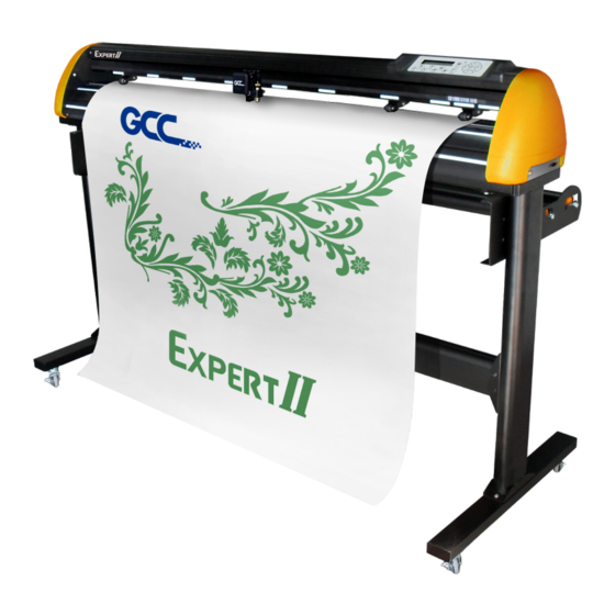
In addition to performing quality cutting on sheet or rolls of media, Expert II series cutting plotters can also be used as a pen plotter. This manual covers the following models of Expert II series cutting plotters: .Ex II-24... -
Page 7: Product Features
Expert II User Manual 1.3 Product Features The followings are the main features of the Expert II cutting plotters: ‧ Dual-port connectivity – USB & Serial interface. ‧ Up to 350 gram cutting force. ‧ Up to 705 (EXII-24(LX) / 635 mm (EXII-52 (LX)) per second cutting speed (at 45 degree direction.) ‧... - Page 8 Expert II User Manual Object Description Primary Pinch Roller To help hold the media during cutting. Slicing Groove To help slice off media. Alignment Ruler To align media with clear guideline marks Tool Carriage Performs the cutting or plotting with the installed blade or pen. Blade Holder To hold the blade.
- Page 9 Expert II User Manual Object Description AC Power Connector To insert the AC power cord. Fuse 3 Amp. Power Switch To turn on or off the machine. USB Connector To connect the machine and a computer through a USB cable. Serial Interface Connector To connect the machine and a computer through a RS-232 cable.
-
Page 10: Installation
Expert II User Manual Chapter 2 Installation 2.1 Precaution Please read below information carefully before you start installation. Notice 1 Make sure the power switch is off before installing the cutting plotter. Carefully handle the cutter to prevent any injuries. Notice 2 Choosing a proper place before setting up the cutting plotter Before installing your cutting plotter, select a suitable location, which meets the following... -
Page 11: Stand Installation
Expert II User Manual Stand Installation (Stand is an optional item for 24 inch models.) 2.2.1 Stand Installation Please follow the procedures below for assembling the stand. Step 1 Please examine the supplied items in the accessory box of the stand carton before you install: Stand is an optional item for Expert II, Item List:... - Page 12 Expert II User Manual Step 3 Place the stand beam upright on the T-stand and put the screws into the holes but do not tighten them at this step. There is hexagon socket head screws fasten on the T-stand on both side taken as locating pins.
- Page 13 Expert II User Manual Step 5 Insert the roll holder support with the screws into the holes of the stand, and then tighten them up as shown in . You could decide roll holder support’s position by inserting into different Figure 2-4 holes.
- Page 14 Expert II User Manual Step 7 The complete picture will be shown like below. ( Figure 2-6 Figure 2-6 Installation...
-
Page 15: Usb Cable Tie And Saddle
Expert II User Manual USB Cable Tie and Saddle The USB cable tie and saddle assembly for the stands with Flexible Media Support System only. Step 1 Insert the cable tie into the upper hole of cable saddle from bottom to top. This side up Step 2 Place the USB cable into the cable tie and tighten the cable tie. - Page 16 Expert II User Manual Pull out the cable tie Pull up the pin Release the cable tie Installation...
-
Page 17: Blade Installation
Expert II User Manual 2.4 Blade Installation Figure 2-7 is the illustrator of the blade holder. Insert a blade into the bottom of Outward ring the blade holder and remove the blade by pushing the pin. Make sure that your fingers Adjustment depth knob are away from the blade tip. - Page 18 Expert II User Manual Step 4 Insert the blade holder into tool carriage. Please note the outward ring of the holder must put into the grooves of carriage firmly (see Figure 2-11), fasten the case (Figure 2-12). Figure 2-11 Figure 2-12 Step 5 Use the reversing steps to remove the blade holder.
-
Page 19: Media Loading
Expert II User Manual 2.5 Media Loading 2.5.1 Loading the Sheet Media To load the media properly, please follow the procedures below: Step 1 Lift the 2 levers at the back side of the cutter to lift the pinch rollers ( Figure 2-13 Figure 2-13 Step 2... - Page 20 Expert II User Manual CAUTION!!! Make sure the Primary and secondary pinch rollers are set to right positions. Position the Primary Pinch Rollers at the right and left sides of media. Position the Secondary Pinch Roller at the center of media. Note: Expert II serves as an illustrator here.
-
Page 21: Loading The Roll Media
Expert II User Manual Note: Always adjust the position with the pinch rollers raised. Please reposition the pinch roller by holding the center of the pinch roller and moving it from the rear end of the machine. (Figure 2-19) ... -
Page 22: Cable Connections
NOTICE: When USB connection is enabled, serial port will be disabled automatically. 2.6.1 USB Interface Expert II series build-in USB interface are based on the Universal Serial Bus Specifications Revision 2.0 (Full Speed). 2.6.1.1 Connecting your GCC cutter 1. Turn on the machine. - Page 23 Expert II User Manual Step 2 You may use search function or directly click the product category to choose the model you want. Installation 2-14...
- Page 24 Expert II User Manual Step 3 Unzip the file and double clip the driver.exe to start installing the Driver and AAS plug-in. Step 4 If you were Windows 7 and above users, please click on the red words to instruct you how to disable Windows Update to allow success driver installation.
- Page 25 Expert II User Manual Step 6 Confirm to close all running application programs before you start installing the driver, and then click OK. Step 7 The installation will take a few minutes to complete and you will see a message below and click on “OK”...
- Page 26 Expert II User Manual Note: (1) If the driver is being installed for a second time, the user will be prompted as to whether a second copy of the driver installation is required. (2) If the user selects yes, a second copy of the driver will be installed. (3) For users who have upgraded Adobe Illustrator or CorelDRAW, please go to the AAS Installer page in the Printer Properties window and click “Install”...
-
Page 27: Driver Un-Installation
Expert II User Manual 2.6.1.3 Driver Un-installation You have to remove previous version driver installed on your PC system completely before you can install the latest version successfully. Please refer to below steps. Step 1 Go to Control Panel\Hardware and Sound\Devices and Printers window. Right click the printer and select “Remove device.”... - Page 28 Expert II User Manual Step 2 After removing the unit, click on any printer on the page and select “Print server properties.” (For Win 7 and above) Or right click on blank space and then select “Print server properties.” (For Windows Step 3 Select “Driver”...
- Page 29 Expert II User Manual Step 4 Select the model and click on “Remove”. Step 5 Select “Remove driver and driver package” and click OK. Step 6 Click Yes and then click “Delete” and “OK,” and the driver installed on PC is completely removed.
-
Page 30: Interface
Expert II User Manual 2.6.2 RS-232 Interface Connecting to the RS-232 (Serial) Port 1. For IBM PC, PS/2 users or compatibles, connect the RS-232C cable to the serial connector of the assigned serial port (COM1 or COM2) of your host computer. 2. -
Page 31: Printer Sever Shared Setting
Expert II User Manual 2.6.4 Printer Sever Shared Setting In “A-PC”, set the printer driver as a shared printer, then use B-PC to connect A-PC’s printer driver via Intranet. A-PC B-PC Intranet USB or COM Port Step 1 Set A-PC’s printer driver as a shared printer (Right-click on printer icon, choose “Printer properties”. - Page 32 Expert II User Manual Step 2 Click “Advanced” tab, then choose “Print directly to the printer” option. Step 3 Send a job from A-PC to the machine to check if A-PC is connected to the machine. Try to send a job to check if the port is working.
- Page 33 Expert II User Manual Step 4 Activate A-PC’s Printer Driver from B-PC’s Network. Step 5 Right-click on the printer icon, and select “Connect” to A-PC’s printer. Installation 2-24...
-
Page 34: Software Installation
Expert II User Manual 2.7 Software Installation 2.7.1 GreatCut-S auto Installation Visit http://gccf.gcc.com.tw/gccclub/login.aspx and log in your GCC Club account. or create a new GCC club account if you do not have one. Click “I Agree”, fill in the required information and click “Submit”... - Page 35 Expert II User Manual You should receive an eMails with activation link and click the link to activate your account. Go to GCC Club, click “GreatCut-S voucher code” on the left side. Enter your voucher code and click “submit”. Installation 2-26...
- Page 36 Expert II User Manual You will get your GreatCut-S serial number. Visit https://www.gccworld.com/download.php click the product category and choose aproper model. Installation 2-27...
- Page 37 Expert II User Manual Download GreatCut-S to start the installation. Press Next to continue, tick “Launch GreatCut-S” and then press “Finish” to compete the installation. Run GreatCut-S and press “Activate…”to activate GreatCut-S. Please make sure it is connected to the internet. Installation 2-28...
-
Page 38: Manually Activate Greatcut-S
Expert II User Manual Enter your name in the Name column and GreatCut-S serial number to the Serial column and press “OK” to complete the activation. 10. GreatCut-S is ready to use. Note If you use a trial version to output graphics, meaning you do not enter the software key to activate the Sure Cuts A Lot mentioned above, there will be two extra lines cut through the... - Page 39 Expert II User Manual Visit https://craftedge.com/activation/greatcut/ via an internet connected computer. Enter your name, serial and site code. Click on the "Generate Activation Code" button, and your activation code will be shown in the Activation Code field. Copy and paste the activation code back into the activation dialog box of Sure Cuts A Lot program and hit ok.
-
Page 40: Re-Install Greatcut-S Software
Expert II User Manual Click OK and GreatCut-S is ready to use. 2.7.3 Re-install GreatCut-S Software If you change a new computer, you may need to deactivate your GreatCut-S software and re-install it on your new device. Go to “Deactivate…” under Help and press Yes to confirm, then follow the installation procedure and use the same code to activate it on another computer. -
Page 41: Reset Greatcut-S Serial Code
Expert II User Manual 2.7.4 Reset GreatCut-S Serial Code If you need to re-install the software again due to problems such as a computer crash/reformat where you were not able to de-activate your copy off the computer first, you may visit https://craftedge.com/activation/deactivateGC.php to reset your serial number Installation... -
Page 42: Operation
Expert II User Manual Chapter 3 Operation 3.1 The Control Panel 3.1.1 The Outline of control panel Figure 3-1 Function POWER LED To indicate the power status ( light up: power on; light off: power off ) ERROR LED To indicate the error status ( light up: error; light off: normal ) To switch modes or stop cutting job( light up: on-line;... - Page 43 Expert II User Manual Step 1 Move the carriage to a new position. Step 2 Press the ORIGIN SET button to reset origin. 3.1.3 Cut Test Note: Make sure the machine is in off-line mode to enable this function. ...
-
Page 44: Vlcd
Expert II User Manual 3.2 VLCD “VLCD” is a computer program to help modify parameters of cutting functions. 3.2.1 Installation Step 1 Download the VLCD.exe file from download area on GCC website onto your local drive to finish installation (Download Area → Vinyl Cutter → Expert II → Software, https://www.gccworld.com/download.php?act=view&id=21) Step 2 Launch VLCD by double-click on the icon. - Page 45 Expert II User Manual 3.2.2 Functions of VLCD Below are the functions adjustable in VLCD for Expert II. Poll Size Blade Force Blade Holder Media Weight Blade Offset AAS Offset Auto Unroll Update ...
- Page 46 Expert II User Manual Media Weight To choose different weights of media in two options: Heavy, and Light (Default). Blade Offset To adjust the blade offset to ensure cutting quality in 8 options: 0.000, 0.175, 0.250 (Default), 0.275, 0.300, 0.500, 0.750, and 1.000. ...
- Page 47 Expert II User Manual 3.2.3 Restore factory default settings VLCD allows you to turn all parameters to factory-default settings. Step 1 Enter the USB-port switching mode by pressing “Pause”(2) after “On/Off line”(1) and then press “Origin Set” (3). Step 2 Press the left key (4) and then up (5) Step 3 You have now entered the Data clear and restoring default settings mode;...
-
Page 48: File Uploader
Expert II User Manual 3.3 File Uploader 3.3.1 Installation “File Uploader” is a tool to help loading files for direct output. The program ONLY supports HPGL format-files generated via GCC Cutter driver. Download the GCC File Uploader.exe file from GCC website onto your local drive to finish installation (Download Area →... -
Page 49: Data Transmission
• SAVE: This function will save current print driver parameter settings to a file under the specified location on your computer. (Saved parameter setting files will be tagged with the Expert II series extension) •... - Page 50 Expert II User Manual settings in Default section cannot be deleted. Please note the delete function only removes the list shown in Custom Media section, it does not remove the file from your hard drive, if you wish to completely remove the file from your hard disk, you will have to manually delete the file from your operating system.
- Page 51 Expert II User Manual To activate the Die Cut function, go to “Option”, tick “Die Cut”, and enter the amount you wish for the “Length” and “Force” of both Die Cut and Kiss Cut, then click “OK” (see figure 3-9). *Note: The length setting for the cutting line of Die Cut is in the...
-
Page 52: Expert Ii Print Driver Setting>Pen Page
Expert II User Manual 3.5.2 Expert II Print Driver setting>Pen Page The Expert series incorporates the use of 6 different colors to represent 6 different parameter settings including cutting speed, force and blade offset settings when cutting. These colors are referred to as “Pens”. - Page 53 Expert II User Manual Note: The GCC Expert series driver cannot store more than 6 pen colors or different cutter parameter settings per file. Speed (Pen Page) [DEFAULT SETTING: 30cm/sec] The speed slider controls the cutter’s cutting speed during operation. Force (Pen Page) [DEFAULT SETTING: 80g] The force slider controls the cutting force during operation.
- Page 54 Expert II User Manual You can adjust the parameter such as force and length in both Pen No.1 and Pen No. 1* as you need. For example: Pen No.1*: Cutting through the backing of the material Pen No.1: Cutting through the vinyl only Sticker Image Scaling (Pen Page) Operation...
-
Page 55: Expert Ii Series Print Driver Setting > Paper Page
3.5.3 Expert II series Print Driver setting > Paper Page Paper Size (Paper Page) [DEFAULT SETTING: Y = the width of machine; X will be automatically set to be twice the length of Y] The paper size represents your total work area. -
Page 56: Reference Parameter Setting For Different Materials
Expert II User Manual 3.6 Reference Parameter Setting for Different Materials The following reference parameter is used on GCC verified materials shown in the table. Personalized/ Wall Material Vehicle stickers Window decoration Window tint stickers Blade red / yellow Blade tip length (mm) 0.28 0.27 0.25... -
Page 57: Basic Maintenance
Expert II User Manual Chapter 4 Basic Maintenance This chapter explains the basic maintenance (i.e. cleaning the cutting plotter) required for the cutting plotter. Except II for the steps mentioned below, all the other maintenances must be performed by a qualified service technician. 4.1 Cleaning the cutting plotter In order to keep the cutting plotter under good conditions and have the best performance, you need to clean the machine properly and regularly. -
Page 58: Cleaning The Grid Drum
Expert II User Manual 4.2 Cleaning the Grid Drum Turn off the cutting plotter, and move the tool carriage away from the area needed to be cleaned. Raise the pinch rollers and move them away from the grid drum for cleaning. ... -
Page 59: Automatic-Aligning System
Expert II User Manual Chapter 5 Automatic-Aligning System AAS II (Automatic-Aligning System II) is only available for Expert II LX models. For Expert II 24 or 52 users, you can skip this chapter. Please note that this chapter is only an instruction to AASII; for step-by-step instructions, please refer to the following chapters: 07_A-4 CorelDraw Plug-In, 07_A-5 Illustrator Plug-In, 07_A-6 GreatCut Plug-In. -
Page 60: Aas Contour Cutting System
Expert II User Manual 5.2 AAS Contour Cutting System The AAS system has one calibration procedures to ensure maximum accuracy of AAS operation. To operate the AAS you need to learn about the method of media feeding firstly. (Refer to 2.4 Media Loading.) 5.2.1 Notice for Registration Marks... -
Page 61: Aas Ii On Expert Ii
Expert II User Manual 5.2.2 AAS II on Expert II There are three types of AAS II mark patterns: 4-Point Positioning, Segmental Positioning, and Multiple Copies. Note that before print out your designs by inkjet printers, the registration marks have to be created on your graphic designs by cutting software like SignPal, GreatCut or GCC CorelDraw plug-in. -
Page 62: Printer Test
Expert II User Manual Layout: 5.3 Printer Test Before performing AAS contour cutting, it’s recommended to print out a test file to make sure the AAS II cutting accuracy. Please visit GCC website and go to Download Area to download the test files. - Page 63 Expert II User Manual There are two testing files for AASII: AAS II_X_Y_Offset_Caberation_A4 .eps (A4 size) AAS II_X_Y_Offset_Caberation_600_600 .eps (Default setting, it is recommended for testing) Print out the testing graphic. ( Please use high precision printer) Load the graphic to Expert II and sent the file to test the cutting job ...
-
Page 64: Registration Mark Offset Range
Expert II User Manual Before adjusting the AAS II settings, please proceed scaling for width and length. The blade offset value isn’t set for this test graphic, please set it according to the blade you use. If you have any question, please contact us or your local distributor for assistance. 5.4 Registration Mark Offset Range Please correctly load your media (refer to the alignment ruler on the platen) to make sure the registration marks are successfully detected. - Page 65 Expert II User Manual Note: The Multiple Copies function is also available. It automatically copy the graphic and registration marks. Step 2 Placing the Registration Marks The AAS Layout Instruction: * Auto-detection function on the 1 mark covers the grey area Suggested 30mm margin on both left and right sides of media sheet.
-
Page 66: Tips For Aas
Expert II User Manual Step 3 Print the Graphics ■ Print the graphic and the marks with your printer (Scaling = 100%). ■ When printing on a roll media, make sure the orientation as following: Step 4 Load the printout onto cutter ■... -
Page 67: Trouble Shooting
Expert II User Manual Chapter 6 Trouble Shooting This chapter helps you to correct some common problems you may come across. Prior to getting into the details of this chapter, please be sure that your application environment is compatible with the cutting plotter. - Page 68 Expert II User Manual 6.2.1 Warning Indicators When the ERROR LED flashes (as shown below), take the necessary actions according to the following instructions. When the problems are solved, the ERROR LED will turn off automatically. Pressing the ON/OFF LINE button can also turn off the ERROR LED. ON/OFF DATA Warning Indicators...
- Page 69 Expert II User Manual Warning 4 Cannot repeat cutting There are two possibilities: 1. There is no data in the buffer: please send the job again from your computer; 2. The buffer is full: please send the same job from your computer again. Under both conditions, press the ON/OFF LINE key to clear the warning message.
- Page 70 Expert II User Manual Error 3 Check the media, drum or X-motor (Drum driven motor) This message indicates that there might be a problem on the X-axis. Please check that the drums are working normally and see that the media is well loaded. Then turn on the power and reboot the cutting plotter.
-
Page 71: Cutting Quality Problems
Expert II User Manual 6.3 Cutting Quality Problems Note: The daily maintenance of your cutting plotter is very important. Be sure to clean up the grid drum and pinch rollers regularly for better cutting accuracy and output quality. Is the blade installed correctly and the blade holder fastened securely? Refer to Chapter 2.3 Is the blade dull... -
Page 72: Expert Ii Specification
Expert II User Manual Expert II Series Specification EX II-24 EX II-24LX EX II-52 Model Number EX II-52LX 600 mm (23.6 in.) 1320 mm (51.96 in) Max. Cutting Width 719 mm (28.3 in.) 1470 mm (57.87 in.) Max. Media Width 0.8 mm... -
Page 73: Blade Specification
Expert II User Manual Blade Specification For cutting thick fluorescent and reflective vinyl. Also for cutting detailed work in standard vinyl. 202003480G The blade is 45° with Red Cap (5-unit package), 0.25 mm offset, and 2.5 mm blade diameter. For cutting reflective vinyl, cardboard, sandblast, flock, and stencil sharp edge. - Page 74 Expert II User Manual About the Tool A generic term referring to the blade that cuts the sheet, the pen that does plotting, and the LED bombsight (option) used for pointing to the reference point. OFFSET is the distance that the blade tip is displaced from the centerline of the blade. Blade Central line Blade tip...
-
Page 75: Coreldraw Output Instruction
Expert II User Manual CorelDRAW Output Instruction The following is an example of how to output the file with CorelDRAW. User Instructions 1. Open CorelDRAW, finish editing all the files you wish to plot and select all the images at once. 2. - Page 76 Expert II User Manual 4. Select “ File → Print” to output the file to your cutters. 5. Choose the correct model you have installed. CorelDRAW Output...
- Page 77 Expert II User Manual 6. Choose the “Layout page” and click the “Reposi on images to: → Bo om le corner”. Please note that you must put your image at the bottom left corner. 7. Go back to the General page and check that your image is at the bottom left corner. Click “Print” and get a wonderful cutting image.
-
Page 78: Coreldraw Plug-In Instruction
Expert II User Manual CorelDRAW Plug-In Instruction AASII VBA Installer is applicable for CorelDRAW Version 13, 14, 15, 16, 17, 18 Installation Please refer to Step 8 in Chapter 2.7.1.2 Driver Installation to install AAS plug-in for CorelDRAW. Run CorelDRAW AAS Plug-in Step 1 Run CorelDRAW to edit your graphics and select all images at once when you wish to plot. - Page 79 Expert II User Manual Step 3 Click on “Apply” and select whether you would like to add the registration marks by page size or by object. Step 4 Now you can print out the image file with registration marks. Note: “Add Registration Mark by Object” will be the default selection if you click on the image whereas “Add Registration Mark by page size”...
- Page 80 Expert II User Manual Add Registration Mark by page size If you tick “Add Registration Mark by page size” as shown in the figure below and click “Apply”, your registration marks will be created automatically (please see Figure A3-1). Note: The length setting will be in the range of 5-25mm according to your page size.
- Page 81 Expert II User Manual Workable area It allows users to edit and cut graphics in the area outside the registration marks when adding registration marks by page. For A4 size media sheet, the workable area is 2.5mm extended from the registration mark on left and right sides and 4.5mm extended from the registration mark on top side.
- Page 82 Expert II User Manual Add Registration Mark by Object If you tick “Add Registration Mark by Object”, you will be offered three options of registration marks as shown below. 4-Point Positioning Length: The length of marks Range: 5mm~50mm ...
- Page 83 Expert II User Manual 4-Point Positioning 4-Point Positioning Length: The length of marks Range: 5mm~50mm Optimized Setting: 25mm Thickness: The line thickness of marks Range: 1mm~2mm Optimized Setting: 1mm Margin: The distance between marks and images ...
- Page 84 Expert II User Manual Note: 1. To save your materials, in addition to amending object margins, you can also adjust the length of the registration marks (5mm minimum) when you apply 4-Point Positioning (see table 1 for suggestions based on different material sizes). The smaller the size is, the smaller the distance between the object and the registration marks is (see the figures below).
- Page 85 Expert II User Manual Segmental Positioning For precise cutting quality, it is suggested to select “Segmental Positioning” when you are working on an extra long or large-sized image to increase cutting accuracy. Segmental Positioning X Step: The distance of intermediate position on the X axis Y Step: The distance of intermediate position on the Y axis ...
- Page 86 Expert II User Manual Multiple Copies It is suggested to select “Multiple Copies” when you would like to make several copies of one image on your material to increase cutting accuracy. Multiple Copies No. of X Copies: The numbers of copies on X axis ...
- Page 87 Expert II User Manual Contour cutting through CorelDraw Step 1 Position the paper with registration marks printed by your printer on the GCC cutter. Step 2 Select “FilesPrint”. Figure A3-13 Note: if you use CorelDraw X5 and later, you must follow the steps below. Step 1 Click the “color”...
- Page 88 Expert II User Manual Step 2 Go to the “Layout” page and select Bottom left corner at “Reposition images to”. Figure A3-15 Step 3 Click “Print”. CorelDRAW Plug-In...
-
Page 89: Illustrator Plug-In Instruction
Expert II User Manual Illustrator Plug-In Instruction AASII VBA Installer is applicable for Adobe Illustrator Version CS4, CS5, CS6, CC. Installation Please refer to Step 8 in Chapter 2.7.1.2 Driver Installation to install AAS plug-in for Adobe Illustrator. Printer Setting Step 1 Go to Control Panel, right click on the printer and select Printer Properties to open the Printer Properties page... - Page 90 Expert II User Manual Step 2 Go to the Advanced page and make sure the “Enable advanced printing features” box is unchecked. Illustrator Plug-In...
- Page 91 Expert II User Manual User Instructions Step 1 Open Illustrator. Step 2 Edit your image and create a contour line (Note: you must have the line width set as 0.001mm). Contour line Step 3 Click on the image and apply the AAS function (FileScripts_AASII_Plug_In). Illustrator Plug-In...
- Page 92 Expert II User Manual Step 4 Select the registration marks needed Step 5 Three types of registration marks are introduced here: 4-Point Positioning, Segmental Positioning and Multiple Copies. Note: The values entered in the “4-Point Positioning” section (length, thickness and margin) will still be applied when you tick “Segmental Positioning”...
- Page 93 Expert II User Manual Step 6 Confirm the registration marks (the 4-Point Position mark is used as an illustration in the following steps). Step 7 Click on the blank area on the page and then click “Document Setup”. Illustrator Plug-In...
- Page 94 Expert II User Manual Step 8 Hit “Edit Artboards”. Step 9 Click on “Presets → Fit Artboard to Artwork bounds”. Illustrator Plug-In...
- Page 95 Expert II User Manual Step 10 Please move your mouse to the tool bar on the left when step 9 is finished and then click “Selection Tool”. Step 11 This will take you back to the edit mode. Illustrator Plug-In...
- Page 96 Expert II User Manual Step 12 Print out the file with the contour line and the registration marks. Step 13 Place the printed file on the cutter, lower the pinch rollers and then position the carriage at the origin of the registration marks. Step 14 Send the file to the cutter.
- Page 97 Expert II User Manual Step 15 Select the cutter model, position the object in the bottom left corner. Step 16 Your job is now completed. Illustrator Plug-In...
- Page 98 Expert II User Manual Add Registration Mark by page size If you want to create registration mark by page size, select the object, go to “Scripts” under “File” and select “_AASII_Plug_In” Tick “Make by page size” and click “Apply” and the registration mark will be created on the 4 corners of the page automatically, sown as below.
- Page 99 Expert II User Manual Workable area It allows users to edit and cut graphics in the area outside the registration marks when adding registration marks by page. For A4 size media sheet, the workable area is 2.5mm extended from the registration mark on left and right sides and 4.5mm extended from the registration mark on top side.
- Page 100 Expert II User Manual Add Registration Mark by Object If you add registration mark by Object, you will be offered three options of registration marks. Firstly, select the graphic which you want to add registration mark on and go to “Scripts” under “File” and select “_AASII_Plug_In”.
- Page 101 Expert II User Manual Three types of registration marks 4-Point Positioning 4-Point Positioning Length: The length of marks Range: 5mm~50mm Optimized Setting: 25mm Thickness: The line thickness of marks Range: 1mm~2mm Optimized Setting: 1mm ...
- Page 102 Expert II User Manual Note: 1. To save your materials, in addition to amending object margins, you can also adjust the length of the registration marks (5mm minimum) when you apply 4-Point Positioning (see table 1 for suggestions based on different material sizes). The smaller the size is, the smaller the distance between the object and the registration marks is (see the figures below).
- Page 103 Expert II User Manual Segmental Positioning For precise cutting quality, it is suggested to select “Segmental Positioning” when you are working on an extra long or large-sized image to increase cutting accuracy. Segmental Positioning X Step: The distance of intermediate position on the X axis ...
- Page 104 Expert II User Manual Multiple Copies It is suggested to select “Multiple Copies” when you would like to make several copies of one image on your material to increase cutting accuracy. Multiple Copies No. of X Copies: The numbers of copies on X axis ...
-
Page 105: Greatcut-S Quick Manual
Expert II User Manual GreatCut-S Quick Manual There are basic instructions of GreatCut-S below. If you need detailed instruction, please refer to GreatCut-S Help. Select the cutter you want to output and change the work area. 1. Run GreatCut-S software. 2. - Page 106 Expert II User Manual 3. Select company / brand as GCC and select model you want to output and then click the “<--Add to list” button. 4. Select GCC on the left and click “Done.” 5. If you want to change the material size and orientation, you can fill a proper value in the Document window.
- Page 107 Expert II User Manual Insert Graphics from Library Select graphics from library to insert a selected design. Draw Text Click on the T icon at left side to create the text and select the font you like at text window. GreatCut-S...
- Page 108 Expert II User Manual Import Design If you have created your design in other design software, go to “import” or “place image” under file to import it, GreatCut-S supports svg, scut, scal, pdf, ai. wpc eps, bmp, gif, jpg and png files. Tips Thousands of SVG files available on SVGCuts! http://SVGCuts.com...
- Page 109 Expert II User Manual 2. Click on “Choose an image” to input the image, adjust Image Settings and Output Settings, and click OK. Then the outline of the image will be outputted automatically. Note The contrast and pixels of import images will affect the trace image result. High contract graphics are recommended.
- Page 110 Expert II User Manual Cut the Design 1. Click on the “Cutter” button on the toolbar and Cut Settings window will pop up. 2. Click on “Settings…” to open GCC Cutter Settings window. Note The origin point is on the bottom right. ...
- Page 111 Expert II User Manual 4. Adjust Blade Offset, Overcut Value, Multi-Cut and Quality under Cut Settings window if needed. *Blade Offset: set the offset value according to different blade, for a standard blade, set the offset value at 0.25mm, 0.5mm for an optional advanced blade and 0mm for an optional plotting pen.
- Page 112 Expert II User Manual 5. Under “Cut Settings” section, there are some useful functions. After setting the parameters, click on “Cut” to send the data to the GCC cutter and the GCC cutter will start the cutting job. *Cut Mode: there are “WSIWYG” and “Origin Point” options, WSIWYG means what you see is what you get, the cutter will output the graphic at same position in preview window.
- Page 113 Expert II User Manual Print and Cut Your Design The Print and Cut function allows you to print the graphics from GreatCut-S to printer, and then put the printed materials on the GCC cutter to cut out the contour of printed jobs from GreatCut-S. Open an image file in GreatCut-S.
- Page 114 Expert II User Manual 3. Click on “Print…” to open printer setting window and click OK. 4. Print your design with registration marks out. 5. Load the printed media to the GCC cutter. 6. Press “Next” and then press “Scan+Cut”, and then the GCC cutter will detect the registration marks and cut the contour lines automatically.
- Page 115 Expert II User Manual Tips Test Connection function can save your materials. Click on “Test Connection” to exam if set the connection properly. GreatCut-S...
- Page 116 Expert II User Manual Cut by Color The Cut by Color function allows you to choose which colors in your design you want to cut, and designate different parameters to each color. You can cut your designs in a single job or separate jobs for each color.
- Page 117 Expert II User Manual 2. Click on “Cut” to open Cut Settings window. 3. Click on the Cut by Color tab and choose to either Cut all Colors in a single job or Cut each color separately as an individual job. When Cut each color separately is selected, GreatCut-S will prompt you between each color before starting to cut so you can load the appropriate color or corresponding tool into your cutting machine.
- Page 118 Expert II User Manual 4. Click on the blade icon to choose the colors you want to cut. The preview will display which colors are currently enabled for cutting. Note: You can adjust the order of the layer arrangement by clicking and dragging the layer. 5.
- Page 119 Expert II User Manual How to create Registration mark in Greatcut-S for contour cutting Step1 Create a file Step2 Go to Windows ➜Dockers ➜GteatCut-S Bridge GreatCut-S...
- Page 120 Expert II User Manual Step3 Select the model with AAS function from the model menu in GreatCut-S Bridge. Step4 Select Contour Outline, and define the offset value of contour line from the size option in Shadow Layer menu. GreatCut-S...
- Page 121 Expert II User Manual Step5 The contour line is created. Step6 Select “Add Reg Marks” to add registration marks. GreatCut-S...
- Page 122 Expert II User Manual Step7 The registration marks are added. Step8 Select “Cut (Add to queue)” to send the file. GreatCut-S...
- Page 123 Expert II User Manual Step9 Clink on “Cut” in GteatCut-S Bridge window. Step10 Define the parameters in Cut Settings window and select “Cut”. Step11 The process is complete. GreatCut-S...
Need help?
Do you have a question about the Expert II Series and is the answer not in the manual?
Questions and answers