Samson 3730-5 Mounting And Operating Instructions
Electropneumatic positioner series 3730
Hide thumbs
Also See for 3730-5:
- Quick start manual ,
- Mounting and operating instructions (160 pages) ,
- Configuration manual (136 pages)
Table of Contents
Advertisement
Quick Links
Download this manual
See also:
Configuration Manual
Advertisement
Table of Contents

Related Manuals for Samson 3730-5


Summary of Contents for Samson 3730-5
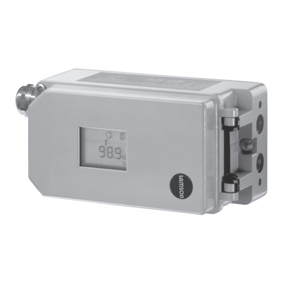
- Page 1 Series 3730 Electropneumatic Positioner Type 3730-5 with F fieldbus communication OUNDATION™ FF Device Rev 1 Fig. 1 · Type 3730-5 Mounting and Operating Instructions EB 8384-5 EN (1300-1614) Firmware version K 1.25/ R 1.46 Edition August 2008...
- Page 2 Definitions of the signal words used in these instructions DANGER! NOTICE DANGER indicates a hazardous situation NOTICE indicates a property damage which, if not avoided, will result in death or message. serious injury. Note: Supplementary explanations, information and tips WARNING! WARNING indicates a hazardous situation which, if not avoided, could result in death or serious injury.
-
Page 3: Table Of Contents
Contents Contents Page Important safety instructions ..... . 9 Article code......11 Design and principle of operation . - Page 4 Contents Limiting the signal pressure ..... . 54 Checking the operating range of the positioner ... . . 54 Initialization .
- Page 5 Contents 16.4.1 Offline operation (indirect data transmission) ... . . 83 16.4.2 Online operation (direct data transmission) ....83 16.4.3 Setting parameters .
- Page 6 Modifications of positioner firmware Modifications of positioner firmware in comparison to previous versions Previous Communication K 1.11 K 1.21 Leakage sensor at binary input 2 The connection of a leakage sensor at binary input 2 (by selecting LEAKAGE SENSOR in CONFIG_BINARY_INPUT2 parameter of the AO Transducer Block) causes: Information specified in XD_ERROR_EXT parameter in the AO Transducer Block and the generation of a diagnostic alarm...
- Page 7 Modifications of positioner firmware Modifications of positioner firmware in comparison to previous versions Previous K 1.23 Internal modifications K 1.24 BUS_ADDRESS parameter The bus address has the default setting of 248. Device type In the delivery state, the device is configured as a basic device. K 1.25 Internal modifications Control R 1.43...
- Page 8 EB 8384-5 EN...
-
Page 9: Important Safety Instructions
Important safety instructions Important safety instructions For your own safety, follow these instructions concerning the mounting, start-up and opera- tion of the positioner: The positioner may only be mounted, started up or operated by trained and experienced personnel familiar with the product. According to these Mounting and Operating Instructions, trained personnel refers to individuals who are able to judge the work they are assigned to and recognize possible dangers due to their specialized training, their knowledge and experience as... - Page 10 Important safety instructions Proper shipping and appropriate storage are assumed. Note: The device with a CE marking fulfills the requirements of the Directives 94/9/EC (ATEX) and 89/336/EEC (EMC). The Declaration of Conformity is available on request. EB 8384-5 EN...
-
Page 11: Article Code
Article code Article code Positioner Type 3730-5 x x x 0 x 0 x x 0 x 0 0 x 0 x x With LCD and autotune, F ™ fieldbus OUNDATION Explosion protection Without II 2 G EEx ia IIC T6 and II 2 D IP 65 T 80 °C (ATEX) -
Page 12: Design And Principle Of Operation
Design and principle of operation When a deviation occurs, the actuator is Design principle pressurized or vented. If required, the operation changes in the signal pressure can be slowed down by a connectable Q restric- The electropneumatic positioner is attached tion. -
Page 13: Additional Equipment
Design and principle of operation The positioner communicates and is pow- can also be issued over the F OUNDATION™ ered using IEC 61158-2 transmission tech- fieldbus network. nology conforming to F OUNDATION™ Version with external position sensor fieldbus specification. In this version, only the sensor is mounted to As a standard feature, the positioner comes the control valve. - Page 14 Design and principle of operation over twisted-pair cables conforming to IEC 61158-2. Note: In the case, complex functions are started in the positioner, which require a long calculation time or lead to a large quantity of data being stored in the volatile memory of the positioner, the alert “busy”...
-
Page 15: Technical Data
OUNDATION™ Fieldbus Communication Profile Class: 31 PS, 32 L; Interoperability tested according to Interoperability Test System (ITK) Revision 4.6 Local Over SAMSON SSP interface and serial interface adapter Software requirements SAMSON TROVIS-VIEW with database module 3730-5 (SSP) Permissible operating 9 to 32 V DC, power supply over bus line · The limits specified in the EC Type... - Page 16 Design and principle of operation Type 3730-5 Positioner with F fieldbus communication OUNDATION –45 to +80 °C Permissible ambient The limits specified in the EC Type Examination Certificate additionally apply for temperature explosion-protected devices Temperature: ≤ 0.15 %/10 K Influences Supply air: None Vibration: ≤...
- Page 17 Design and principle of operation Options for Type 3730-5 Binary contact 2 for floating contact R < 100 Ω, contact loadability 100 mA, static destruction limit 20 V / 5.8 mA, Switching input galvanically isolated Solenoid valve Approval acc. to IEC 61508/SIL 24 V DC, reverse polarity protection, static destruction limit 40 V −...
-
Page 18: Attachment To The Control Valve - Mounting Parts And Accessories
The positioner is standard equipped with the lever M (pin position 35). The positioner is suitable for the following types of attachment: Direct attachment to SAMSON Type 3277 Actuator Attachment to actuators according to IEC 60534-6 (NAMUR) Attachment to Type 3510 Micro-flow... - Page 19 [cm²] [mm] Min. Travel Max. 25.0 120/240/350 35.0 355/700 10.0 50.0 Attachment according to IEC 60534-6 (NAMUR) SAMSON valves/Type 3271 Actuator Other valves/actuators Required Assigned Actuator size Rated travel lever pin position [cm²] [mm] min. Travel max. 60 and 120 with 18.0...
-
Page 20: Direct Attachment
Attachment to the control valve – Mounting parts and accessories Direct attachment ing towards the signal pressure connec- tion. Make sure that the bonded gasket 4.1.1 Type 3277-5 Actuator (14) points towards the actuator yoke. 5. 15 mm travel: Keep the follower pin (2) Refer to Table 1 on page 40 for the required at lever M (1) on the back of the mounting parts as well as the accessories... - Page 21 Attachment to the control valve – Mounting parts and accessories Symbols Switchover plate (9) Lever 1.1 Nut Actuator stem 1.2 Disk spring extends Follower pin Follower clamp Vent plug Attachment left Attachment right Stopper Connecting plate Actuator stem 6.1 Seal rings retracts Pressure gauge bracket Press.
-
Page 22: Type 3277 Actuator
Attachment to the control valve – Mounting parts and accessories 4.1.2 Type 3277 Actuator rests on the top of the follower clamp (3). Adjust the lever (1) correspondingly Refer to Table 2 on page 41 or the required and open the positioner cover to hold mounting parts as well as the accessories the positioner shaft in position at the cap with their order numbers. - Page 23 Attachment to the control valve – Mounting parts and accessories Lever 12.1 Screw 1.1 Nut 12.2 Stopper or connection for external piping 1.2 Disk spring Switch plate Follower pin 10 14 Gasket Follower clamp Formed seal 10 Cover plate Gasket 11 Cover 12 Connection block Lever M...
-
Page 24: Attachment According To Iec 60534-6
Attachment to the control valve – Mounting parts and accessories Attachment according to 3. Mount connecting plate (6) or pressure gauge bracket (7) with pressure gauges IEC 60534-6 (8) on the positioner, making sure both Refer to Table 3 on page 41 for the required seal rings (6.1) are seated properly. - Page 25 Attachment to the control valve – Mounting parts and accessories Attachment to rod-type yoke Rod diameter 20 to 35 mm Attachment to NAMUR rib Additional bracket for actuators with 2800 cm and travel ≥ 60 mm Lever Lever XL and L 14.1 Disk spring Follower pin...
-
Page 26: Attachment To Type 3510 Micro-Flow Valve
Attachment to the control valve – Mounting parts and accessories Attachment to Type 3510 Micro-flow Valve Refer to Table 3 on page 41 for the required mounting parts as well as the accessories with their order numbers. Note the travel table on page 19! The positioner is attached to the valve yoke using a bracket. - Page 27 Attachment to the control valve – Mounting parts and accessories Lever Disk spring Follower pin Clamp Connecting clamp Seal rings Pressure gauge bracket Pressure gauge mounting kit Bracket Screw Note: Always use the connecting plate (6) included in the accessories to connect supply and output.
-
Page 28: Attachment To Rotary Actuators
90°. Prior to attaching the positioner to the 7. Place positioner on the top pair of SAMSON Type 3278 Rotary Actuator, mount the associated adapter (5) to the free brackets (10) and screw tight. Con- end of the rotary actuator shaft. - Page 29 Attachment to the control valve – Mounting parts and accessories (7, 8) 10.1 80 mm Note: Always use the connecting plate (6) included in the accessories to connect 130 mm supply and output. Never screw threaded parts directly into the Slot housing.
-
Page 30: Heavy-Duty Version
(11) underneath, if der no.1400-6964) into the signal pres- necessary. sure output of the positioner (or the out- 2. For SAMSON Type 3278 and VETEC put of the pressure gauge bracket or S160 Rotary Actuator, screw the adapter connecting plate). - Page 31 4.2 Disk spring 4.3 Adhesive label Actuator shaft or adapter 5.1 Adapter 10.1 10.1 SAMSON Type 3278 Attachment acc. to VDE/VDI 3845 VETEC S160, VETEC R level 2 Fig. 11 · Attachment to rotary actuators (heavy-duty version) EB 8384-5 EN...
-
Page 32: Reversing Amplifier For Double-Acting Actuators
5. Use a screwdriver (8 mm wide) to screw positioner must be fitted with a reversing the enclosed filters (1.6) into the con- amplifier, e.g. the SAMSON Type 3710 Re- necting boreholes A and Z. versing Amplifier (see Mounting and Oper- ating Instructions EB 8392 EN). - Page 33 Attachment to the control valve – Mounting parts and accessories From the positioner Output 38 Supply 9 Control signals to the actuator Reversing amplifier Connecting plate 6.1 O-rings 1.1 Special screws 1.2 Gasket 6.2 Screws 1.3 Special nuts 1.4 Rubber seal 1.5 Sealing plug 1.6 Filter Fig.
-
Page 34: Attaching An External Position Sensor
Attachment to the control valve – Mounting parts and accessories Operation and setting are described in Attaching an external sections 6 and 7. position sensor – Since 2009, the back of the position sen- sor (20) is fitted with two pins acting as Refer to Table 6 on p. - Page 35 Attachment to the control valve – Mounting parts and accessories tracts" the connection on the top diaphragm in pin position 35 on the sensor. If nec- case is used. The connection at the side of essary, remove the follower pin (2) from the yoke must be fitted with a venting plug its pin position and move it to the bore- (accessories).
-
Page 36: Mounting The Position Sensor With Attachment According To Iec 60534-6
Attachment to the control valve – Mounting parts and accessories Screw tight the mounting plate (21) onto lever together with the disk spring (1.2) the actuator yoke using both fixing from the sensor shaft. screws. 2. Screw the position sensor (20) onto the 7. -
Page 37: Mounting The Position Sensor To Type 3510 Micro-Flow Valve
Attachment to the control valve – Mounting parts and accessories the follower plate (3) and fix with the 2. Screw the position sensor (20) onto the screws (14.1). bracket (21). 5. Place the bracket with the sensor at the 3. Select the lever S (1) from the accesso- NAMUR rib in such a manner that the ries and screw the follower pin (2) into follower pin (2) rests in the slot of the fol-... -
Page 38: Mounting The Position Sensor To Rotary Actuators
Attachment to the control valve – Mounting parts and accessories 4.6.4 Mounting the position 4. Place the lever (1) and disk spring (1.2) on the sensor shaft. sensor to rotary actuators Place the lever (1) in mid-position and For the required mounting parts and the ac- hold it in place. -
Page 39: Attaching Positioners With Stainless Steel Housings
Attachment to the control valve – Mounting parts and accessories Attaching positioners with Air purging function for stainless steel housings single-acting actuators Positioners with stainless steel housings re- The exhaust air from the positioner is di- quire mounting parts that are completely verted to the actuator spring chamber to made of stainless steel or free of aluminum. -
Page 40: Required Mounting Parts And Accessories
Attachment to the control valve – Mounting parts and accessories Should other valve accessories be used which vent the actuator (e.g. solenoid valve, volume booster, quick exhaust valve), this exhaust air must also be included in the purging function. The connection over the adapter at the positioner must be protected with a check valve (e.g. - Page 41 Attachment to the control valve – Mounting parts and accessories Order no. Table 2 · Direct attachment to Type 3277 Actuator (Fig. 5) Mounting Attachment to actuators with 240, 350, 355, 700 cm 1400-7453 parts Steel 1400-6444 240 cm Stainless steel 1400-6445 Required piping with screw fittings Steel...
- Page 42 Can only be used in combination with TROVIS-VIEW 6661-1058 TROVIS-VIEW with device module 3730-5 (order no. 6661-1058) 1262295 Serial interface adapter (SAMSON SSP interface - RS-232 port on computer) 1400-7700 Isolated USB interface adapter (SAMSON SSP interface - USB port on computer) 1400-9740 EB 8384-5 EN...
- Page 43 CrNiMo steel bracket, see Fig. 17 Attachment to VDI/VDE 3845 for all sizes of fixing level 2, heavy-duty version 1400-9384 rotary actuators SAMSON Type 3278 with 160 cm (also for VETEC Type S160 and Type R), 1400-9385 heavy-duty version 1400-7461...
-
Page 44: Connections
Connections Blow through all air pipes and hoses tho- Connections roughly prior to connecting them. WARNING! Mount the positioner, keeping the following If the positioner is attached directly to the sequence: Type 3277 Actuator, the connection of the 1. Mount the positioner on the control valve positioner's output pressure to the actuator 2. -
Page 45: Signal Pressure (Output)
Connections Actuator stem retracts FE (AIR TO CLOSE) Electrical connections Fail-safe position "Valve Open" (for globe and angle valves): DANGER! For tight-closing valves, the maximum signal Risk of electric shock and/or pressure pst is roughly estimated as fol- the formation of an explosive lows: atmosphere! –... - Page 46 Connections Note on the selection of cables and wires: For the interconnection of equipment to en- ergy-limited circuits with type of protection To install intrinsically safe circuits, observe EEx nL IIC, the permissible maximum val- section 12 of EN 60079-14: 2003 ues specified in the statement of conformity (VDE 0165 Part 1).
- Page 47 Connections 3. Strip the insulation off the end of the bus NOTICE line to the required connecting length To connect the limit switch, binary inputs, and cut the wire shield off up to a length and forced venting, an additional cable of approx.
-
Page 48: Establishing Communication
Connections Limit switch 5.2.1 Establishing communication For operation of the limit switches, switching The communication structure between the amplifiers have to be connected in the out- controller, logic solvers (PLC) or automation put circuit. Their function is to control the system, or between a PC or work station limit values of the control circuit according and the positioner(s) is implemented to con-... - Page 49 Connections Power conditioner Power Conditioner Power supply unit Speisegerät Control system Leitsystem OUNDATION TM fieldbus EN 61158-2 OUNDATION TM Bus termination fieldbus Terminierung EN 61158-2 3730-50 3730-50 3730-50 3730-50 Power conditioner Power Conditioner Power supply unit Control system Speisegerät Leitsystem OUNDATION TM fieldbus Ex fieldbus barrier/isolator...
-
Page 50: Operator Controls And Readings
Operator controls and readings Readings on display Operator controls readings Icons appear on the display that are as- signed to parameters, codes and functions. Rotary pushbutton Operating modes: The rotary pushbutton is located underneath Manual mode (MAN), section 8.2.1 the front protective cover. Automatic mode (AUTO), section 8.2.1 The positioner is operated on site using the Fail-safe position (SAFE), section 8.2.2... - Page 51 Operator controls and readings Displays and their meaning AUtO Automatic mode Reset together Clockwise Start AO Transducer Block is in the MAN mode, see page 140 Counterclockwise SAFE Fail-safe position Error Substitute calibration blinking Emergency mode Escape Initialization in progress TunE (see error code 62 on p.
-
Page 52: Start-Up - Settings
Start-up – Settings Start-up – Settings NOTICE Perform the start-up settings in the same se- quence as listed (section 7.1 to section 7.6). WARNING! Attach the positioner, keeping the following sequence: Note: The positioner performs a test in the 1. Mount the positioner on the control valve start-up phase while following its automa- 2. -
Page 53: Setting The Volume Restriction Q
(MAX). The position of volume restriction Q also de- pends on how the signal pressure is routed Reading direction for left at the actuator in SAMSON actuators: attachment of pneumatic connections The “SIDE“ position applies for actuators with a loading pressure connection at the side, e.g. -
Page 54: Limiting The Signal Pressure
Start-up – Settings → Code 2 Turn Limiting the signal pressure: → Code 2 blinks. Press → Required direction Turn Pressure limit Default: OFF Press to confirm reading direction. Limiting the signal pressure → Code 16 Turn → Code 16 blinks. Press If the maximum actuator force may cause damage to the valve, the signal pressure... -
Page 55: Initialization
Start-up – Settings Checking the operating range: fore exchanging the lever or changing the pin position. Manual reference variable w (current angle of rotation Initialization is indicated) WARNING! → Code 1 Turn During initialization, the control valve moves → Code 1 and Press blink. - Page 56 Start-up – Settings valves with two clearly defined mechani- cal end positions, e.g. three-way valves Initialization successful, (see section 7.6.1) positioner in automatic operating mode NOM nominal range Initialization mode for all globe valves (see section 7.6.2) The time required for an initialization pro- MAN manually selected range cess depends on the transit time of the actu- Initialization mode for globe valves with...
-
Page 57: Max - Initialization Based On Maximum Range
Start-up – Settings Reference variable Valve closed Direction of Valve position action Closed at Open at Default OFF ää AIR TO OPEN 100 % äæ AIR TO CLOSE 100 % → Code 3 , display: OFF Turn The tight-closing function is activated. →... -
Page 58: Nom - Initialization Based On Nominal Range
Start-up – Settings Enter the pin position: Enable configuration: Note: If no settings are entered within Pin position 120 seconds, the enabled configuration Default OFF function becomes invalid. → Code 4 Turn Press , Code 4 blinks Default OFF → Pin position on lever (see rele- Turn vant section on attachment) Press... -
Page 59: Man - Initialization Based On A Manually Selected Range
Start-up – Settings → Nominal travel/angle Turn Enable configuration: Press Note: If no settings are entered within 120 seconds, the enabled configuration Select the initialization mode: function becomes invalid. Initialization mode Default MAX Default OFF → Code 6 Turn Press , Code 6 blinks →... -
Page 60: Sub Substitute Calibration
Start-up – Settings Select the initialization mode: 7.6.4 SUb substitute calibration A complete initialization procedure takes several minutes and requires the valve to Initialization mode move through its entire travel range several Default MAX times. This initialization mode, however, is an emergency mode, in which the control parameters are estimated and not deter- →... - Page 61 Start-up – Settings Select the initialization mode: Default OFF Initialization mode Default MAX → Code 3 Turn Press , Code 3 blinks → Code 6 Turn → ON Turn Press , Code 6 blinks Press , display → SUb Turn Press to confirm the SUb as the initializa- Enter the pin position and nominal range:...
- Page 62 Start-up – Settings Change pressure limit and control parame- Enter closing direction and blocking posi- ters: tion: Closing direction Note: Do not change the pressure limit Direction of rotation caus- ing the valve to move to the (Code 16). Only change the control param- CLOSED position (view eters K (Code 17) and T...
-
Page 63: Zero Calibration
Start-up – Settings Start initialization: parameters K and T must be slightly cor- rected. Proceed as follows: Press INIT key! Set T to 4 (Code 18). The positioner switches to manual oper- If the positioner still oscillates, the gain K ating mode. -
Page 64: Reset To Default Values
Start-up – Settings Press , display Reset start-up parameters: Perform zero calibration: Reset Default OFF Initialization mode Default MAX → Code 36 Turn Press , Code 36 blinks → Code 6 Turn → RUN Turn Press , Code 6 blinks Press . -
Page 65: Operation
Operation You can now configure codes one after the Operation other: Turn and select the required code. WARNING! The actuator stem moves while the positioner Press to access the selected code. The is being operated. code number starts to blink. Do not touch the actuator stem or obstruct it Turn and select the setting. -
Page 66: Safe - Fail-Safe Position
Operation Note: The positioner automatically returns to manual mode with Code 0 if no settings automatic mode are made within 120 seconds. Switch to automatic operating mode → Code 0 Turn Switch to manual operating mode Press , Code 0 blinks. →... -
Page 67: Malfunction/Maintenance Alarm
Operation Turn and select the required operating demand or above average wear has mode AUtO or MAN . been determined. The wear tolerance will soon be exhausted or is reducing at Press . The positioner switches to the op- a faster rate than expected. Mainte- erating mode selected. -
Page 68: Confirming Error Messages
Status and diagnostic alarms Status and diagnostic alarms Example The Type 3730-5 Positioner contains inte- Error caused by pin position grated diagnostics to generate classified sta- tus and diagnostic alarms. There are two different types of on-board di- agnostics available: the standard integrated... -
Page 69: Extended Expert + Diagnostics
Note: Details on extended EXPERT diagnos- tics can be found in the Operating Instruc- Online test functions (monitoring functions) tions EB 8388-5 EN available on the Internet at http://www.samson.de. Data logger Histograms Cycle counter Valve end position trend y = f (x) diagram (drive signal) -
Page 70: Adjusting The Limit Switch
Adjusting the limit switch The desired switching function, i.e. whether Adjusting the limit switch the output relay shall be picked up or re- The positioner version with an inductive limit leased when the tag has entered the field, switch has one adjustable tag (1) mounted has to be determined, if necessary, at the on the shaft which operates the proximity switching amplifier. - Page 71 Adjusting the limit switch For CLOSED position: 1. Initialize positioner. 2. Use the MAN function to move the positioner to 5 % (see LC display). 3. Adjust the tag using the yellow adjust- ment screw (2) until the tag enters or leaves the field and the switching ampli- fier responds.
-
Page 72: Retrofitting An Inductive Limit Switch
Retrofitting an inductive limit switch Retrofitting an inductive limit switch Required retrofit kit: Limit switch Order no. 1400-7460 Note! For explosion-protected devices, the requirements in section 13 need to be kept. 1. Take off the rotary pushbutton (3) and cap (1), unthread the five fixing screws (2) and lift off the plastic cover (9). -
Page 73: Maintenance
SAMSON especially for this purpose to rule out any damage to components relevant for explo- sion protection. - Page 74 NOTICE Laptops and PCs connected to the power supply can only be interconnected to intrin- sically safe equipment if a SAMSON iso- lated USB interface adapter is connected be- tween computer and device when perform- ing test routines or programming software.
-
Page 75: Fieldbus Specification
OUNDATION™ types of blocks. Each type of block has a different range of tasks to fulfill in the block model. The following types of blocks are implemented in the SAMSON Type 3730-5 Positioner: One Resource Block The Resource Block contains all the specific characteristics associated with a device on the Fieldbus, for example, device name, manufacturer number and serial number. -
Page 76: Resetting The Device
Fieldbus specification The AO Function Block converts the output value from an upstream function block into a control value for the valve. Execution time: 20 ms Two Discrete Input Function Blocks The DI Function Blocks are used as inputs to control binary signals. They support the se- lection of binary switching conditions of various functions. - Page 77 Fieldbus specification To provide a better overview, the classified alarms are summarized in a condensed state (CONDENSED_STATE (59) in RES Block). Besides the CONDENSED_STATE parameter, the condensed state can be issued to the discrete output OUT_D of the DI Function Blocks. Possible states of the condensed state include: Maintenance The positioner still performs its control task (with restrictions).
-
Page 78: Settings In Trovis-View Software
Operator Interface. It is not possible to link function blocks of other devices with the TROVIS-VIEW software. The TROVIS-VIEW software containing online help and the da- tabase module for Type 3730-5 Positioner is delivered on a CD-ROM (order number 6661-1058). Software updates are available in Internet (http://www.samson.de) in Services >... -
Page 79: Installing Trovis-View Software
2. Follow the on-screen prompts and instructions of the installation program. The TROVIS-VIEW Operator Interface can be used for different SAMSON devices. Note that the installation program also offers you the option of installing a demo module. To use the... -
Page 80: Starting Trovis-View And Performing Basic Settings
Settings in TROVIS-VIEW software 16.3 Starting TROVIS-VIEW and performing basic settings You can perform the settings in TROVIS-VIEW either when the positioner is connected (on- line) to the computer or not connected (offline). Note: When the positioner is not connected, the default settings appear on the operator in- terface or, alternatively, a stored TROVIS-VIEW file (*.tro) can be loaded and overwritten by selecting Open in the File menu. - Page 81 5. Set the communications port for data communication. Proceed as follows: Connect the port (RS-232 or USB) of the computer using the corresponding adapter to the SAMSON SSP interface of the positioner. Select Communications in Options menu to open the server settings window. Click Server settings button.
-
Page 82: Data Transmission
Settings in TROVIS-VIEW software Converting the software version The TROVIS-VIEW software version must match the firmware of the positioner. On exchanging data between the positioner and TROVIS-VIEW, the software automatically checks whether the versions are compatible and, if necessary, converts the data. If you want to adapt the firmware version without exchanging any data, proceed as follows: 1. -
Page 83: Offline Operation (Indirect Data Transmission)
Settings in TROVIS-VIEW software Data from the positioner are uploaded and shown in the operator interface. The complete set of data is downloaded to the positioner from the operator interface. To transfer individual parameters, open the corresponding context-sensitive menu. Select Write to just download the selected parameter, refer to section 16.4.3. -
Page 84: Setting Parameters
Settings in TROVIS-VIEW software Activate online operation: Select Online in Device menu to activate online mode. In online mode, on the device toolbar is animated. Deactivate online operation: Select Online in Device menu while the online mode is acti- vated. The online mode is canceled. Note! Alternatively, click on the device toolbar to activate and deactivate online operation. - Page 85 Settings in TROVIS-VIEW software Parameters are data points whose settings can be changed. They are marked by the icon. Their settings can be made either in online or offline mode. 1. Click on one of the folders in the left tree directory to view the parameter settings on the right.
-
Page 86: Initializing The Positioner And Performing An Operational Test
Settings in TROVIS-VIEW software 16.5 Initializing the positioner and performing an operational test Initializing the positioner and performing an operational test are only possible in TROVIS-VIEW when the positioner has been attached properly to the control valve and has been connected (see sections 4 and 5). The positioner must be connected to the computer over the serial interface adapter. - Page 87 Settings in TROVIS-VIEW software 3. Start initialization by right-clicking Initialization and selecting Execute . How long the initialization procedure lasts depends on the actuator transit time and may take a few minutes. Operational test 1. Start the test mode by clicking icon.
-
Page 88: Status Classification
Settings in TROVIS-VIEW software 16.6 Status classification Alarms are classified in the positioner with a status when an error occurs. States include “Maintenance alarm“, “Maintenance required“, “Maintenance demanded “, “Function check“ and “No message“. Maintenance alarm The positioner cannot perform its control task due to a functional fault in the device or in one of its peripherals or an initialization has not yet been successfully completed. - Page 89 Settings in TROVIS-VIEW software To provide a better overview, the classified alarms are summarized in a condensed state which is made up from a summary of all classified positioner alarms. The condensed state appears in TROVIS-VIEW3 on the right-hand side of the info bar and in the Diagnosis folder (>...
-
Page 90: Appendix
Appendix Appendix 17.1 Code list Parameter – Display, values Code Description [default setting] Note: Codes with marked with an asterisk (*) must be enabled with Code 3 prior to configuration. Operating mode Switchover from automatic to manual mode is smooth. In fail-safe mode, the symbol S appears on the display. - Page 91 Appendix Parameter – Display, values Code Description [default setting] Note: Codes with marked with an asterisk (*) must be enabled with Code 3 prior to configuration. Pin position The follower pin must be inserted into the correct pin position ac- cording to the valve travel/angle of rotation.
- Page 92 Appendix Parameter – Display, values Code Description [default setting] Note: Codes with marked with an asterisk (*) must be enabled with Code 3 prior to configuration. Direction of action of the reference variable w in relation to the travel/angle of rotation x [ää] increasing/increasing äæ...
- Page 93 Appendix Parameter – Display, values Code Description [default setting] Note: Codes with marked with an asterisk (*) must be enabled with Code 3 prior to configuration. Travel/angle upper limit Limitation of the travel/angle of rotation upwards to the entered (upper x-limit) value, the characteristic is not adapted.
- Page 94 Appendix Parameter – Display, values Code Description [default setting] Note: Codes with marked with an asterisk (*) must be enabled with Code 3 prior to configuration. Proportional-action Displaying or changing K coefficient KP (step) Note on changing the K and T steps: 0 to 17 [7] During the initialization of the positioner, the K...
- Page 95 0 to 9 [0] Linear Equal percentage Reverse equal percentage SAMSON butterfly valve linear SAMSON butterfly valve equal percentage VETEC rotary plug valve linear VETEC rotary plug valve equal percentage Segmented ball valve linear Segmented ball valve equal percentage User-defined (defined over operating software) Note: The various characteristics are listed in the Appendix (section 19).
- Page 96 Appendix Parameter – Display, values Code Description [default setting] Note: Codes with marked with an asterisk (*) must be enabled with Code 3 prior to configuration. LV total valve travel Limit value of total valve travel. If the limit is exceeded, the fault symbol and the wrench symbol corresponding with the collective 1000 to 99 ·...
- Page 97 Appendix Parameter – Display, values Code Description [default setting] Note: Codes with marked with an asterisk (*) must be enabled with Code 3 prior to configuration. y info Display only. [0] to 100 % Indicates the control signal y in % based on the travel range de- termined on initialization 0P, MAX, –...
- Page 98 Appendix Parameter – Display, values Code Description [default setting] Note: Codes with marked with an asterisk (*) must be enabled with Code 3 prior to configuration. d6 Condensed status Condensed status, made up from the individual states. OK: Okay C: Maintenance required CR: Maintenance demanded B: Maintenance alarm I: Function check...
- Page 99 Appendix Parameter – Display, values Code Description [default setting] Note: Codes with marked with an asterisk (*) must be enabled with Code 3 prior to configuration. A7 Out Status and its status Displays the current block error A8 Block Error PID Function Block P P0 Target Mode Required operating mode...
- Page 100 Appendix Parameter – Display, values Code Description [default setting] Note: Codes with marked with an asterisk (*) must be enabled with Code 3 prior to configuration. S1 Resource Actual Mode Actual operating mode S2 Resource Block Error Displays the current block error DI1Function Block I I0 Target Mode DI1 Required operating mode...
- Page 101 Appendix Initialization errors Error codes – Recommended action Condensed state alarm active, when prompted, Err appears. When fault alarms exist, they are displayed here. The value supplied by the measuring signal is either too high or x > range too low, the measuring sensor is close to its mechanical limit. •...
- Page 102 Appendix Error codes – Recommended action Condensed state alarm active, when prompted, Err appears. When fault alarms exist, they are displayed here. The initialization routine lasts too long. Initialization time exceeded (Init time >) • No pressure on the supply line or there is a leak. •...
- Page 103 Appendix Operational errors Error codes – Recommended action Condensed state alarm active, when prompted, Err appears. When fault alarms exist, they are displayed here. Control loop error, the control valve does not react within the tol- Control loop erable times of the controlled variable (tolerance band alarm Code 19).
- Page 104 Status classification [Maintenance demanded] Recommended action Return the positioner to SAMSON AG for repair. The circuit of the i/p converter has been interrupted. i/p converter Status classification Maintenance alarm (cannot be classified) Recommended action Cannot be remedied.
- Page 105 Test calculation The hardware controller is monitored by means of a test calculation. Status classification Maintenance alarm (cannot be classified) Recommended action Confirm error. If this is not possible, return the positioner to SAMSON AG for repair. EB 8384-5 EN...
- Page 106 Error in the production calibration data. Subsequently, the device runs on default values. Status classification [Maintenance required] Recommended action Return the positioner to SAMSON AG for repair. General parameters Parameter errors that are not critical for the control. Status classification [Maintenance required] Recommended action Confirm error.
- Page 107 Status classification Maintenance alarm (cannot be classified) Recommended action Interrupt current and restart positioner. Otherwise, return the positioner to SAMSON AG for repair. Options parameter Errors in options parameters Status classification [Maintenance required] Recommended action Return the positioner to SAMSON AG for repair. EB 8384-5 EN...
- Page 108 Appendix Diagnosis errors Error codes – Recommended action Condensed state alarm active, when prompted, Err appears. When fault alarms exist, they are displayed here. Diagnostic alarms Alarms are generated by the extended EXPERT diagnostics if EXPERT has been activated under Code 48 Status classification Maintenance required (cannot be classified) Diagnostic parameters Errors that are not critical for control.
-
Page 109: Parameters
In the Device Description Library supplied by Fieldbus Foundation upon which the device description of 3730-5 is also based, these parameters are incorrectly specified as the unit of ms. The specified values supplied by the device are, however, always to be interpreted as the unit of 1/32 ms. -
Page 110: Discrete Input Transducer Blocks
The CHANNEL parameter is used to assign the Transducer Blocks to the function blocks. The Type 3730-5 Positioner has two binary inputs that work independently from one an- other. A Discrete Input Function Block exists for each input. - Page 111 Appendix Fig. 24 · Analog Output Transducer Block EB 8384-5 EN...
-
Page 112: Analog Output Function Block
The Fault State is determined over FSTATE_TIME, FSTATE_VAL and IO_OPTS parameters. In the Device Description Library supplied by Fieldbus Foundation upon which the device description of 3730-5 is also based, "Fault state to value" is indicated as "Fault state type" in the IO_OPTS parameter of the AO Function Block. - Page 113 Appendix XD_SCALE 100 % READBACK PV_SCALE 0 °C SP_LO_LIM<=SP<=SP_HI_LIM Output Set point Set point PV, XD action ramps limitation scaling SP_HI_LIM SP_RATE_DN XD_SCALE IO_OPTS SP_LO_LIM SP_RATE_UP PV_SCALE MODE_BLK MODE_BLK PV, XD scaling (manual) READBACK XD_SCALE, PV_SCALE Fig. 25 · Analog Output Function Block EB 8384-5 EN...
-
Page 114: Discrete Input Function Block Di1
Appendix 17.2.5 Discrete Input Function Block DI1 The Type 3730-5 Positioner is fitted with a standard contact input to process binary voltage signals. The Discrete Input DI1 Function Block is used for processing the contact input (terminals 87 und 88) and to integrate a F fieldbus application. -
Page 115: Discrete Input Function Block Di2
Appendix 17.2.6 Discrete Input Function Block DI2 The Type 3730-5 Positioner is optionally fitted with a binary input to process a floating con- tact. The Discrete Input DI2 Function Block is used for processing the contact input (terminals 85 und 86) and to integrate a F fieldbus application. -
Page 116: Pid Function Block
Appendix 17.2.7 PID Function Block A PID Function Block contains the input channel processing, the proportional-integral-deriva- tive (PID) control loop and the analog output channel processing. The configuration of the PID Block (PID controller) depends on the automation task. Simple control loops, control loops with manipulate variable feedforwarding, cascade con- trol and cascade controls with limitation in combination with another controller function block can be implemented. - Page 117 Appendix Derivative component: In controlled systems with long delay times, e.g. in temperature control loops, it is better to use the derivative component RATE of the controller. Using the derivative component RATE, the manipulated variable is calculated depending on the rate of change of the sys- tem deviation.
-
Page 118: Other Parameters
Appendix 17.3 Other parameters 17.3.1 Stale Counter The Stale Counter serves to judge the “quality” of a process variable received over a config- ured cyclic connection (publisher/subscriber connection). These connections are used to transfer the process variable linked amongst the various func- tion blocks. -
Page 119: Parameter Lists
Appendix 17.4 Parameter lists Legend SK (class of memory): Static parameter Dynamic parameter Non-volatile parameter Read/write Read capability capability: Write capability (access) Supported modes: O/S (out of service) mode MAN mode AUTO mode Cascade mode RCAS Remote cascade mode O/M/A/CAS/RCAS Not analyzed Other modes: Local override mode... - Page 120 Appendix Resource Block Resource Block Parameter Index Access Mode Selection/display, [initial value] ACK_OPTION [Undefined] . . . No selection DISC ALM . . . Write lock changed BLOCK ALM . . Block alarm ALARM_SUM DISC ALM . . . Write lock changed BLOCK ALM .
- Page 121 Resource Block Appendix Description Determines whether an alarm is to be automatically acknowledged in the positioner, i.e. without intervention of the fieldbus host system. Note: The alarm is broadcast to the fieldbus host system, but not acknowledged by it. Determines the current state of the process alarms in the Resource Block. Used to specify the identification number of the plant section.
- Page 122 Index Access Mode Selection/display, [initial value] DD_REV DESCRIPTOR DEV_REV DEV_TYPE 2 for Type 3730-5 DEVICE_CERTIFICATION DEVICE_PRODUCT_ NUM DEVICE_SER_NUM DEVICE_MESSAGE FAULT_STATE FEATURES FEATURES_SEL REPORTS ......
- Page 123 Indicates the memory in percent available for implementation of additional function blocks. Note: This parameter is not supported as no further function blocks may be added to the Type 3730-5. Indicates the block processing time in percent that is free to process additional blocks.
- Page 124 Index Access Mode Selection/display, [initial value] LOCAL_OP_ENA MANUFAC_ID 0 x 00E099 = SAMSON AG MAX_NOTIFY MEMORY_SIZE MIN_CYCLE_T 640 1/32 ms MODE_BLK AUTO .......
- Page 125 Specifies the maximum number of alert reports that the device can send without getting a confirmation. Indicates the memory in kilobytes available for additional function blocks. Note: This parameter is not supported as no further function blocks may be added to the Type 3730-5. Indicates the shortest cycle interval that the device can perform (execution time of AO function block 20 ms).
- Page 126 Appendix Resource Block Parameter Index Access Mode Selection/display, [initial value] Continued DI1/2 condensed state ....SELECT_BINARY_ INPUT1 SELECT_BINARY_ INPUT2 SET_FSTATE SHED_RCAS SHED_ROUT [640000 1/32 ms] ST_REV STRATEGY...
- Page 127 Resource Block Appendix Description . . 0 OK 1 Maintenance required 2 Maintenance demanded 3 Maintenance alarm 7 Function check Enables manual activation of the Fault State of the Analog Output Function Block. Determines how long function blocks are supposed to check that the connection between the fieldbus host system and the PID Block exists in RCAS mode.
- Page 128 Appendix Resource Block Parameter Index Access Mode Selection/display, [initial value] WRITE_PRI [0]........1.
- Page 129 Resource Block Appendix Description Used to set the priority for the WRITE_ALM parameter. . . The write-lock alarm is not processed. . . The write-lock alarm is not broadcast to fieldbus host system. . . Reserved for block alarms . . The write-lock alarm is issued to notify the operator with the corresponding priority (3 = low, 7 = high). .
- Page 130 Appendix Analog Output Transducer Block Analog Output Transducer Block Parameter Index Access Mode Selection/display, [initial value] ACT_FAIL_ACTION UNINITIALIZED..Undefined CLOSING..(in 0 % position) OPENING ..(in 100 % position) INDETERMINATE .
- Page 131 Analog Output Transducer Block Appendix Description Sets the fail-safe action to be performed by the actuator in case of a supply air failure, determined automatically during initialization. Specifies the actuator manufacturer’s identification number. Clearly identifies the manufacturer of the actuator used with the positioner. Specifies the type/model number of the actuator used with the positioner.
- Page 132 Appendix Analog Output Transducer Block Parameter Index Access Mode Selection/display, [initial value] BLOCK_ERR OUT OF SERVICE ..... . . DEVICE NEEDS MAINTENANCE NOW..DEVICE NEEDS MAINTENANCE SOON .
- Page 133 Indicates and modifies the blocking position (see Code 35). Indicates and modifies the closing direction (see Code 34). This parameter is not processed by Type 3730-5. Sets the logic state of DI2. The parameter is processed by the BINARY_INPUT2 parameter. The parameter settings do not depend on Transducer Block DI2.
- Page 134 Appendix Analog Output Transducer Block Parameter Index Access Mode Selection/display, [initial value] DELAY_TIME 1 to 240 s, [10 s] O/M/A DEVIATION_MAX DEVIATION_MIN DEVICE_ O/M/A CHARACTERISTICS ACTUATOR_SIZE ACTUATOR_VERSION ATTACHMENT PRESSURE_RANGE_START PRESSURE_RANGE_END SUPPLY_PRESSURE DEVICE_INIT_STATE DIAG_LEVEL EXPERT . . . Standard valve diagnostics EXPERT .
- Page 135 Analog Output Transducer Block Appendix Description Specifies the delay time (reset criterion when control loop monitoring is in progress). If the entered DELAY_TIME is exceeded and the system deviation is outside the specified TOLERANCE_BAND, a control loop error is issued. Determined from the minimum transit time during initialization.
- Page 136 Appendix Analog Output Transducer Block Parameter Index Access Mode Selection/display, [initial value] ERROR_OPTION_ENH_ O/M/A DIAGNOSTIC_1 ERROR_OPTION_ENH_ O/M/A DIAGNOSTIC_5 ERROR_OPTION_HW_ O/M/A FAILURE 1. . x signal 2. . i/p converter ERROR_OPTION_INIT_ O/M/A FAILURE 1. . x > range 2. . Delta x < range 3.
- Page 137 Analog Output Transducer Block Appendix Description Specifies the masking of diagnostic status or error alarms. Specifies the masking of hardware errors. 3. . Hardware 5. . Control calculation 4. . Data memory 6. . Program loading error Specifies the masking of initialization errors. 4.
- Page 138 Appendix Analog Output Transducer Block Parameter Index Access Mode Selection/display, [initial value] FINAL_VALUE_ O/M/A CUTOFF_HI_ON FINAL_VALUE_ –2.5 to 100 %, [1 %] O/M/A CUTOFF_LO FINAL_VALUE_ O/M/A CUTOFF_LO_ON FINAL_VALUE_RANGE FINAL VALUE RANGE EU_100 (see Code 9) FINAL VALUE RANGE EU_0 (see Code 8) FINAL VALUE RANGE UNITS_INDEX FINAL VALUE RANGE DECIMAL HIS_TEMPERATURE...
- Page 139 Analog Output Transducer Block Appendix Description Enables the final position w > (see Code 15). Final position if set point falls below adjusted value (see Code 14). If the set point falls below the adjusted value, the valve is moved to the final position that corresponds to 0 % of the manipulated variable.
- Page 140 0 to 120 s, [1 s] O/M/A LIN_TYPE O/M/A 1. . Linear 2. . Equal percentage 3. . Equal percentage reverse 4. . SAMSON butterfly linear LOGGING_LIMIT O/M/A 1. . Lower limit 2. . Upper limit MODE_BLK O/M/A AUTO Automatic ..... . .
- Page 141 (reverse step change). Available in versions with EXPERT extended diagnostics and higher. Sets the characteristic (see Code 20) 5. . SAMSON butterfly equal percentage 9. Segmented ball valve equal percentage 6. . VETEC rotary linear 10. User defined 7.
- Page 142 Appendix Analog Output Transducer Block Parameter Index Access Mode Selection/display, [initial value] NO_OF_ZERO_ POINT_ADJ OVERSHOOT_FALLING OVERSHOOT_RISING PRESSURE_LIMIT O/M/A 1. . Off ..3. . 2.4 bar 2. . 3.7 bar ..4. . 1.4 bar PRESSURE_Y PRETRIGGER_TIME O/M/A...
- Page 143 Analog Output Transducer Block Appendix Description Specifies the number of zero calibrations performed since the last initialization. Evaluation parameter for step response test. Overshooting of falling reference variable step change. Available in versions with EXPERT extended diagnostics and higher. Evaluation parameter for step response test. Overshooting of rising reference variable step change. Available in versions with EXPERT extended diagnostics and higher.
- Page 144 Appendix Analog Output Transducer Block Parameter Index Access Mode Selection/display, [initial value] SELF_CALIB_CMD O/M/A 1 . . No test, normal operation 2 . . Start with default values 3 . . Start initialization 4 . . Abort initialization 5 . . Start zero point adjustment 6 .
- Page 145 7 . . Controller optimization 11 . . Terminated 8 . . Fine adjustment This parameter is not processed by Type 3730-5. Allows the valve to be moved to its actual fail-safe position. Fail-safe position is indicated by an S blinking on the display.
- Page 146 Appendix Analog Output Transducer Block Parameter Index Access Mode Selection/display, [initial value] STEP_PROGRESS STEP_SAMPLE_RATE [0.1] to 120 s O/M/A STEP_SELECTION O/M/A 1. . One step 2. . Two steps STEPEND 0 to [100 %] O/M/A STEPSTART [0] to 100 % O/M/A STRATEGY O/M/A...
- Page 147 Analog Output Transducer Block Appendix Description The progress of the step response test is indicated. Available in versions with EXPERT extended diagnostics and higher. Used to set the sampling rate of the step response logging Available in versions with EXPERT extended diagnostics and higher.
- Page 148 Appendix Analog Output Transducer Block Parameter Index Access Mode Selection/display, [initial value] TRANSDUCER_ DIRECTORY TRANSDUCER_STATE 1. . See operating mode 2. . Solenoid valve active 3. . Lower travel limit active TRANSDUCER_TYPE TRANSM_PIN_POS O/M/A TRAVEL_LOWER_LIMIT O/M/A TRAVEL_LOWER_LIMIT_ O/M/A TRAVEL_RATE_DEC O/M/A TRAVEL_RATE_INC O/M/A TRAVEL_UPPER_LIMIT...
- Page 149 Analog Output Transducer Block Appendix Description This parameter is not processed in Type 3730-5. Indicates the state of the Transducer Block. 4. . Upper travel limit active 7. . Fail-safe position active 5. . End position < active 8. . Normal operation 6.
- Page 150 Appendix Analog Output Transducer Block Parameter Index Access Mode Selection/display, [initial value] VALVE_TYPE O/M/A UNINITIALIZED......[LINEAR] ......ROTARY .
- Page 151 Appendix Description Type of valve Note! The Type 3730-5 differentiates merely between linear and rotary valves . . (Type 3730-5: Treated like a globe valve) . . (Control valves with straight moving plug, e.g. globe valves) . . (Control valves with rotating closure members) .
- Page 152 Appendix Analog Output Transducer Block Parameter Index Access Mode Selection/display, [initial value] ZERO_POINT_LIMIT O/M/A Parameter index Index Parameter Index Parameter Index Parameter ADVANCED_PV_BASIC ACT_MAN_ID ERROR_OPTION_ENH_ DIAGNOSTIC_2 ST_REV ACT_MODEL_NUM ERROR_OPTION_ENH_ TAG_DESC ACT_SN DIAGNOSTIC_3 STRATEGY VALUE_MAN_ID ERROR_OPTION_ENH_ DIAGNOSTIC_4 ALERT_KEY VALUE_MODEL_NUM ERROR_OPTION_ENH_ MODE_BLK VALVE_SN DIAGNOSTIC_5 BLOCK_ERR...
- Page 153 Analog Output Transducer Block Appendix Description Indicates the zero point limit [%] Index Parameter Index Parameter Index Parameter TRANSM_PIN_POS TRAVEL_RATE_DEC DIAG_LEVEL INIT_METHOD PRESSURE_LIMIT HYS_STELL_Y SELF_CALIB_CMD ENHANCED_DIAG_CMD STEPSTART SUB_MODE_INIT ELAPSED_HOURS_METERS STEPEND SELF_CALIB_STATUS NO_OF_ZERO_POINT_ STEP_SAMPLE_RATE DEVICE_INIT_STATE ERRORBYTE ZERO_POINT_LIMIT MOVING_DIRECTION RAMP_UP COUNTER_INIT_START CLOSING_DIRECTION RAMP_DOWN EVENT_LOGGING_1 ACT_STROKE_TIME_DEC...
- Page 154 Appendix Analog Output Function Block Analog Output Function Block Parameter Index Access Mode Selection/display, [initial value] ALERT_KEYS 1 to 255, [0] “0” is not a permissible value and will be rejected when transferring data to the device (error alarm). BKCAL_OUT BLOCK_ALM BLOCK_ERR OUT OF SERVICE .
- Page 155 Note: This value is used when the option “Fault State to value” is set in the IO_OPTS parameter. Grants or denies access of a fieldbus host system to the field device. Note: This parameter is not used by Type 3730-5. EB 8384-5 EN...
- Page 156 Appendix Analog Output Function Block Parameter Index Access Mode Selection/display, [initial value] IO_OPTS SP-PV Track in MAN..... Track in LO ......SP Track retained target .
- Page 157 Analog Output Function Block Appendix Description Used to select how the input/output is processed in the AO Block . . The set point tracks the process variable in MAN mode (ACTUAL_MODE) SP-PV . . The set point tracks the process variable in LO mode (ACTUAL_MODE) .
- Page 158 Appendix Analog Output Function Block Parameter Index Access Mode Selection/display, [initial value] RCAS_OUT READBACK Value determined from FINAL_POSITION_ VALUE parameter of the associated Transducer Block. Unit from XD_SCALE parameter group SHED_OPT [Uninitialized] ......NormalShed_NormalReturn .
- Page 159 Analog Output Function Block Appendix Description Display of analog reference variable (value and status) after ramping. This value is provided to the fieldbus host system for back calculation to allow action to be taken under mode changes or limited signals. Note: This parameter is only active in the RCAS mode.
- Page 160 Appendix Analog Output Function Block Parameter Index Access Mode Selection/display, [initial value] SP_RATE_DN [3402823466 x 10 SP_RATE_UP [3402823466 x 10 ST_REV STATUS_OPTS [Uninitialized] ......Propagate Fault Backward .
- Page 161 Analog Output Function Block Appendix Description Used to enter the ramp rate for downward set point changes in AUTO mode. Note: The set point is used immediately when the ramp rate is set to zero. The rate limit is active for output blocks in the AUTO and CAS modes.
- Page 162 Appendix Discrete Input Function Block Discrete Input Function Block 1 Parameter Index Access Mode Selection/display, [initial value] ACK_OPTION [0] ..No selection O/M/A BLOCK_ALM . . Block alarm DISC_ALM ..Discrete alarm ALARM_SUM O/M/A BLOCK_ALM .
- Page 163 Indicates the discrete input value of the DI1 Function Block with details on the status. Grants or denies access of a fieldbus host system to the field device. Note: This parameter is not processed by Type 3730-5. Used to select how the input/output is processed in the DI1 Block.
- Page 164 Appendix Discrete Input Function Block Parameter Index Access Mode Selection/display, [initial value] MODE_BLK O/M/A AUTO ....... MAN .
- Page 165 Discrete Input Function Block Appendix Description Indicates the actual mode of the DI1 Block, the permitted modes supported by the DI1 Block, and the normal mode. . . The binary input value FIELD_VAL_D is processed by the Function Block and issued as OUT_D. .
- Page 166 Appendix PID Function Block PID Function Block Parameter Index Access Mode Selection/display, [initial value] ACK_OPTION [Undefined] ......HI_HI_ALM .
- Page 167 PID Function Block Appendix Description Used to select whether an alarm is to be automatically acknowledged in the positioner, i.e. without intervention of the Fieldbus host system. Note: The alarm is broadcast to the fieldbus host system, but not acknowledged by it. .
- Page 168 Appendix PID Function Block Parameter Index Access Mode Selection/display, [initial value] BKCAL_HYS 0 to 50 %, [0.5 %] BKCAL_IN BKCAL_OUT BLOCK_ALM BLOCK_ERR OUT OF SERVICE ..... . . CONFIGURATION_ERROR .
- Page 169 PID Function Block Appendix Description Used to specify the amount the manipulated variable must change away from its range limits OUT_HI_LIM and OUT_LO_LIM before the limit status is turned off. If the manipulated variable moves off a limit, in percent of scale, the limit status is indicated in the OUT parameter and passed on to the following blocks.
- Page 170 Appendix PID Function Block Parameter Index Access Mode Selection/display, [initial value] DV_HI_ALM DV_HI_LIM [3402823466 x 10 DV_HI_PRI [0]........1.
- Page 171 PID Function Block Appendix Description Indicates deviation high alarm status including details of time of alarm (date and time stamp) as well as the value that triggered the alarm. The controlled variable exceeds the reference variable by more than the value determined in DV_HI_LIM parameter. The setting for the alarm limit used to detect the deviation high alarm condition.
- Page 172 Appendix PID Function Block Parameter Index Access Mode Selection/display, [initial value] GRANT_DENY HL_ALM Unit from PV_SCALE HI_HI_ALM Unit from PV_SCALE HI_HI_LIM Range and unit from PV_SCALE, [3402823466 x 10 HI_HI_PRI [0]........1.
- Page 173 Grants or denies access of a fieldbus host system to the field device. Note: This parameter is not used by Type 3730-5. Indicates high alarm status (HI_LIM) including details of time of alarm (date and time stamp) as well as the value that triggered the alarm.
- Page 174 Appendix PID Function Block Parameter Index Access Mode Selection/display, [initial value] LO_LO_PRI [0]........1.
- Page 175 PID Function Block Appendix Description Determines the action to be taken when the value for the low low alarm is not reached (LO_LO_LIM). . . The limit for low low alarm is not processed. . . Alarm is not broadcast to fieldbus host system. .
- Page 176 Appendix PID Function Block Parameter Index Access Mode Selection/display, [initial value] PV_FTIME [0 s] PV_SCALE [0 to 100 %] RATE [0 s] RCAS_IN RCAS_OUT RESET [3402823466 x 10 (max. possible value]) ROUT_IN ROUT_OUT EB 8384-5 EN...
- Page 177 PID Function Block Appendix Description Used to enter the filter time constant (in seconds) of the first-order digital filter. This time is needed to allow a 63 % change of the input IN in the value of PV to become effective. Definition of the range (initial and final values), the engineering unit and the number of decimal places used for the process variable (PV).
- Page 178 Appendix PID Function Block Parameter Index Access Mode Selection/display, [initial value] SHED_OPT [Uninitialized] ......NormalShed_NormalReturn ....NormalShed_NoReturn .
- Page 179 PID Function Block Appendix Description Determines what action is to be taken when the monitoring time is exceeded (see SHED_RCAS parameter in the Resource Block) while the connection between the fieldbus host system and the PID Block in RCAS or ROUT mode is being checked.
- Page 180 Appendix PID Function Block Parameter Index Access Mode Selection/display, [initial value] STATUS_OPT [Uninitialized] ......IFS if Bad IN ......IFS if Bad CAS_IN .
- Page 181 PID Function Block Appendix Description Allows the selection of status options available to determine the handling and processing of the status: . . Trigger IFS substate of downstream AO Function Block, of the input value (IN) changes the status to BAD. .
-
Page 182: Dimensions In Mm
Dimensions in mm Dimensions in mm Pressure gauge Attachment acc. to IEC 60534-6 or connecting plate bracket External position sensor Lever mm S = 17 M = 50 L = 100 XL = 200 Direct attachment M20 x 1.5 Output (38) Supply (9) Fig. - Page 183 Dimensions in mm Output Y Output Y Supply (9) Output Y Output Y Type 3710 Reversing Amplifier Ø 101 (optional) Output A1 Supply (9) Reversing amplifier Output A2 1079-1118 1079-1119 (option) Connecting plate G ¼ or ¼ NPT Fig. 29b · Attachment to rotary actuators VDI/VDE 3845 for all sizes of fixing level 2 EB 8384-5 EN...
-
Page 184: Valve Characteristic Selection
Valve characteristic selection Valve characteristic selection The characteristics that can be selected in Code 20 are shown in following in graph form. Note: A characteristic can only be defined (user-defined characteristic) using a workstation/ operating software (e.g. TROVIS-VIEW). Linear (select characteristic: 0) Travel/ angle of rotation [%] Reference variable [%] Equal percentage (select characteristic: 1) - Page 185 SAMSON butterfly valve linear SAMSON butterfly valve equal percentage (select characteristic: 3) (select characteristic: 4) Travel/ angle of rotation [%] Travel/ angle of rotation [%] Reference variable [%] Reference variable [%] VETEC rotary plug valve linear VETEC rotary plug valve equal percentage...
- Page 186 EB 8384-5 EN...
-
Page 187: Text Certificates
EB 8384-5 EN... - Page 188 EB 8384-5 EN...
- Page 189 EB 8384-5 EN...
- Page 190 EB 8384-5 EN...
- Page 191 EB 8384-5 EN...
- Page 192 EB 8384-5 EN...
- Page 193 EB 8384-5 EN...
- Page 194 EB 8384-5 EN...
- Page 195 EB 8384-5 EN...
- Page 196 EB 8384-5 EN...
- Page 197 EB 8384-5 EN...
- Page 198 EB 8384-5 EN...
- Page 199 EB 8384-5 EN...
- Page 200 EB 8384-5 EN...
- Page 201 EB 8384-5 EN...
- Page 202 EB 8384-5 EN...
- Page 203 EB 8384-5 EN...
- Page 204 EB 8384-5 EN...
- Page 205 EB 8384-5 EN...
- Page 206 EB 8384-5 EN...
- Page 207 EB 8384-5 EN...
- Page 208 SAMSON AG · MESS- UND REGELTECHNIK Weismüllerstraße 3 · 60314 Frankfurt am Main · Germany Phone: +49 69 4009-0 · Fax: +49 69 4009-1507 EB 8384-5 EN Internet: http://www.samson.de...
Need help?
Do you have a question about the 3730-5 and is the answer not in the manual?
Questions and answers