Table of Contents
Advertisement
Quick Links
Installation Instructions
MicroLogix™ 1200 Thermocouple/mV Input
Module
(Catalog Number 1762-IT4)
Inside...
Module Overview......................................................................................2
Description ................................................................................................3
Module Installation...................................................................................3
System Assembly......................................................................................5
Mounting...................................................................................................6
Field Wiring Connections..........................................................................8
Cold-Junction Compensation (CJC) ........................................................13
I/O Memory Mapping .............................................................................13
Specifications .........................................................................................16
Hazardous Location Considerations .......................................................21
Environnements dangereux ....................................................................22
For More Information..............................................................................23
Advertisement
Table of Contents

Related Manuals for Rockwell Automation MicroLogix 1200


Summary of Contents for Rockwell Automation MicroLogix 1200
-
Page 1: Table Of Contents
Installation Instructions MicroLogix™ 1200 Thermocouple/mV Input Module (Catalog Number 1762-IT4) Inside… Module Overview..................2 Description ....................3 Module Installation...................3 System Assembly..................5 Mounting....................6 Field Wiring Connections................8 Cold-Junction Compensation (CJC) ............13 I/O Memory Mapping ................13 Specifications ..................16 Hazardous Location Considerations ............21 Environnements dangereux ..............22 For More Information................23 Publication 1762-IN013A-EN-P - April 2002... -
Page 2: Module Overview
MicroLogix™ 1200 Thermocouple/mV Input Module Module Overview The thermocouple/mV modules receives and stores digitally converted thermocouple and/or millivolt (mV) analog data from any combination of up to four thermocouple or millivolt analog sensors. Each input channel is individually configurable via software for a specific input device and provides open-circuit, over-range and under-range detection and indication. -
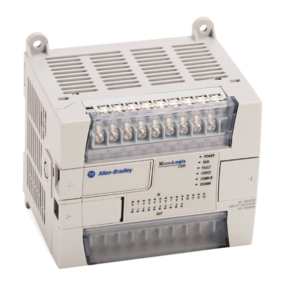
Page 3: Description
MicroLogix™ 1200 Thermocouple/mV Input Module Description Item Description Item Description upper panel mounting tab bus connector cover lower panel mounting tab flat ribbon cable with bus connector (female) power diagnostic LED terminal block module door with terminal identification DIN rail latch label bus connector with male pins pull loop... - Page 4 MicroLogix™ 1200 Thermocouple/mV Input Module Prevent Electrostatic Discharge Electrostatic discharge can damage integrated circuits or ATTENTION semiconductors if you touch bus connector pins. Follow these guidelines when you handle the module: • Touch a grounded object to discharge static potential. •...
-
Page 5: System Assembly
MicroLogix™ 1200 Thermocouple/mV Input Module System Assembly The expansion I/O module is attached to the controller or another I/O module by means of a ribbon cable after mounting as shown below. Use the pull loop on the connector to disconnect modules. Do not pull on the ribbon cable. -
Page 6: Mounting
Failure to remove strip before operating can cause overheating. Minimum Spacing Maintain spacing from enclosure walls, wireways, adjacent equipment, etc. MicroLogix 1200 Side Side Allow 50.8 mm (2 in.) of space on all sides for adequate ventilation, as... - Page 7 MicroLogix™ 1200 Thermocouple/mV Input Module DIN Rail Mounting The module can be mounted using the following DIN rails: 35 x 7.5 mm (EN 50 022 - 35 x 7.5) or 35 x 15 mm (EN 50 022 - 35 x 15). Before mounting the module on a DIN rail, close the DIN rail latch.
-
Page 8: Field Wiring Connections
MicroLogix™ 1200 Thermocouple/mV Input Module Field Wiring Connections Grounding the Module This product is intended to be mounted to a well-grounded mounting surface such as a metal panel. Additional grounding connections from the module’s mounting tabs or DIN rail (if used), are not required unless the mounting surface cannot be grounded. - Page 9 MicroLogix™ 1200 Thermocouple/mV Input Module • For millivolt inputs, always use Belden™ 8761 (shielded, twisted-pair) or equivalent wire to ensure proper operation and high immunity to electrical noise. • If multiple power supplies are used with millivolt analog inputs, the power supply commons must be connected.
- Page 10 MicroLogix™ 1200 Thermocouple/mV Input Module Wiring the Finger-Safe Terminal Block Be careful when stripping wires. Wire fragments that fall into ATTENTION a module could cause damage when power is applied. Once wiring is complete, ensure the module is free of all metal fragments.
- Page 11 MicroLogix™ 1200 Thermocouple/mV Input Module Wire Size and Terminal Screw Torque Each terminal accepts up to two wires with the following restrictions: Wire Type Wire Size Terminal Screw Torque Solid Cu-90°C (194°F) #14 to #22 AWG 0.904 Nm (8 in-lbs) Stranded Cu-90°C (194°F) #16 to #22 AWG...
- Page 12 MicroLogix™ 1200 Thermocouple/mV Input Module 5. Connect the signal wires to the module terminal block and input. 6. Repeat steps 1 through 5 for each channel on the module. Terminal Block with CJC Sensor and Thermocouple Junctions IN 0+ grounded thermocouple CJC sensor CJC+ IN 0-...
-
Page 13: Cold-Junction Compensation (Cjc)
MicroLogix™ 1200 Thermocouple/mV Input Module Cold-Junction Compensation (CJC) To obtain accurate readings from each of the channels, the temperature at the terminal junction between the thermocouple wire and the input channel must be compensated for. A cold-junction compensating thermistor has been integrated in the terminal block, as shown on page 12. - Page 14 MicroLogix™ 1200 Thermocouple/mV Input Module Input Data File For each module, slot x, words 0 through 3 contain the analog values of the inputs. The input data file is shown below. Word/ Analog Input Data Channel 0 Analog Input Data Channel 1 Analog Input Data Channel 2 Analog Input Data Channel 3 Reserved...
- Page 15 MicroLogix™ 1200 Thermocouple/mV Input Module Make these bit settings To Select 15 14 13 12 11 10 10 Hz 60 Hz 50 Hz 250Hz 500 Hz 1 kHz Upscale Downscale Hold Last State Zero Degrees C Degrees F Thermocouple J Thermocouple K Thermocouple T Thermocouple E...
-
Page 16: Specifications
MicroLogix™ 1200 Thermocouple/mV Input Module Module Configuration Word Word 4 of the configuration data file contains the Enable/Disable Cyclic Calibration bit as shown in the table below. To Select Make these bit settings 15 14 13 12 11 10 Cyclic Enabled Calibration Disabled... - Page 17 MicroLogix™ 1200 Thermocouple/mV Input Module Specification Value Electrical /EMC: The module has passed testing at the following levels: ESD Immunity (EN61000-4-2) 4 kV contact, 8 kV air, 4 kV indirect Radiated Immunity (EN61000-4-3) 10 V/m, 80 to 1000 MHz, 80% amplitude modulation, +900 MHz keyed carrier Fast Transient Burst (EN61000-4-4) 2 kV, 5 kHz...
- Page 18 MicroLogix™ 1200 Thermocouple/mV Input Module Input Specifications Continued Specification 1762-IT4 See “Repeatability” on page 20. Repeatability Maximum Overload at Input ±35V dc continuous Terminals Module Error over Full Temperature See “Input Accuracy” on page 19. Range (0 to +55°C [+32°F to +131°F]) CJC Accuracy ±1.3°C (±2.34°F) Power Supply Distance Rating...
- Page 19 The module uses the National Institute of Standards and Technology (NIST) ITS-90 standard for thermocouple linearization. Accuracy is dependent upont the analog/digital converter output rate selection, data format, and input noise. Refer to the MicroLogix 1200 Thermocouple/mV Input Module User’s Manual , publication number 1762-UM002A, for additional information.
- Page 20 MicroLogix™ 1200 Thermocouple/mV Input Module Repeatability Input Type Repeatability for 10 Hz Filter at 25°C [77°F] Themocouple J ±0.1°C [±0.18°F] Themocouple N (-110°C to +1300°C [-166°F to +2372°F]) ±0.1°C [±0.18°F] Themocouple N (-210 to -110°C [-346°F to -166°F]) ±0.25°C [±0.45°F] Themocouple T (-170°C to +400°C [-274°F to +752°F]) ±0 .1°C [±0.18°F] Themocouple T (-270°C to -170°C [-454°F to -274°F])
-
Page 21: Hazardous Location Considerations
MicroLogix™ 1200 Thermocouple/mV Input Module Hazardous Location Considerations This equipment is suitable for use in Class I, Division 2, Groups A, B, C, D or non-hazardous locations only. The following WARNING statement applies to use in hazardous locations. EXPLOSION HAZARD WARNING •... -
Page 22: Environnements Dangereux
MicroLogix™ 1200 Thermocouple/mV Input Module Environnements dangereux Cet équipement est conçu pour être utilisé dans des environnements de Classe 1, Division 2, Groupes A, B, C, D ou non dangereux. La mise en garde suivante s’applique à une utilisation dans des environnements dangereux. DANGER D’EXPLOSION AVERTISSEMENT •... -
Page 23: For More Information
• download a free electronic version from the internet: www.ab.com/micrologix or www.theautomationbookstore.com • purchase a printed manual by: – contacting your local distributor or Rockwell Automation representative – visiting www.theautomationbookstore.com and placing your order – calling 1.800.963.9548 (USA/Canada) or 001.330.725.1574 (Outside USA/Canada) -
Page 24: Publication 1762-In013A-En-P - April
MicroLogix is a trademark of Rockwell Automation. Belden is a trademark of Belden, Inc. Publication 1762-IN013A-EN-P - April 2002 PN 40071-145-01(1) Copyright © 2002 Rockwell Automation. All rights reserved. Printed in the U.S.A. ´H'+M!¶1b¨...
Need help?
Do you have a question about the MicroLogix 1200 and is the answer not in the manual?
Questions and answers