Venmar 41502 User Manual
Heat recovery ventilators and
energy recovery ventilators
Hide thumbs
Also See for 41502:
- Installation manual (18 pages) ,
- User's and installer's manual (18 pages)
Advertisement
H
R
EAT
E
NERGY
C
ONSTRUCTO
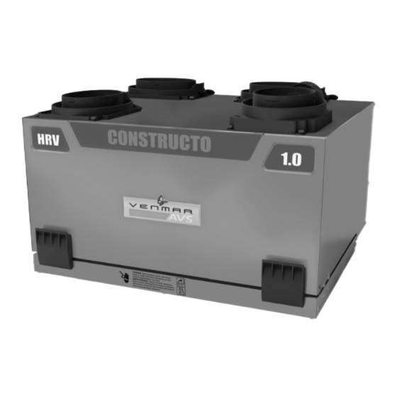
Model no.: 41502
(HRV with ports on top)
VB0069
Model no.: 41506
(ERV with ports on top)
VB0071
User Guide
ECOVERY
R
ECOVERY
P
LEASE READ AND SAVE THESE INSTRUCTIONS
V
ENTILATORS AND
V
ENTILATORS
1.0
MODELS
Model no.: 41500
(HRV with ports on sides)
VB0070
Model no.: 41504
(ERV with ports on sides)
VB0074
:
.
06009A rev. B
Advertisement
Table of Contents

Related Manuals for Venmar 41502


Summary of Contents for Venmar 41502
- Page 1 User Guide ECOVERY ENTILATORS AND NERGY ECOVERY ENTILATORS ONSTRUCTO MODELS Model no.: 41502 Model no.: 41500 (HRV with ports on top) (HRV with ports on sides) VB0070 VB0069 Model no.: 41506 Model no.: 41504 (ERV with ports on top) (ERV with ports on sides)
- Page 2 Congratulations! You have made an excellent choice! The operating principle of your Heat Recovery Ventilator or Energy Recovery Ventilator will give you personnal comfort you have never known before. We have prepared this User Guide especially for you. Please read it carefully to ensure you obtain full benefit from your unit.
-
Page 3: Table Of Contents
Table of contents 1.0 Defrosting Mode ......... . 2 2.0 Controls . -
Page 4: Controls
2.0 Controls 2.1 Integrated Control All units are equipped with an integrated control, located under the unit, in front of the electrical compartment. Use the push button (1) to control the unit. The LED (2) will then shows on which mode the unit is in. WARNING AVERTISSEMENT Risk of electric shock. - Page 5 2.0 Controls (cont’d) 2.2 Optional Main Controls (cont’d) 2.2.1 Lite-Touch Constructo Activate the push button; the color of the indicator shows the unit operating mode. INTERMITTENT VC0075 OLOR UGGESTED REEN NTERMITTENT ELECT THIS MODE WHEN YOU ARE AWAY FROM THE HOUSE FOR A FEW DAYS WHEN YOU DEEM THE INSIDE AIR IS TOO DRY IN HEATING SEASON...
- Page 6 2.0 Controls (cont’d) 2.2 Optional Main Controls (cont’d) 2.2.3 Constructo AIR SUPPLY CONTROL DJUSTING Select speed «MIN» or «MAX» using 5°C 41°F OFF MIN MAX slide switch (A). -5°C 23°F • When «MIN» (minimum speed) is -20°C -4°F selected, if the knob (B) is set above the click, the unit will exchange in low speed with the outside and if it is set below the click, the unit will exchange...
-
Page 7: Optional Auxiliary Controls
2.0 Controls (cont’d) 2.3 Optional Auxiliary Controls Contrary to the optional main controls, up to 5 optional auxiliary controls can be connected to the same ventilation unit. 2.3.1 20-minute lighted push button Press once to activate the push button. The unit will operate on high speed for 20 minutes and the indicator will light up. -
Page 8: Maintenance
3.0 Maintenance WARNING Risk of electric shock. Before performing any maintenance or servicing, always disconnect the unit from its power source. Since this guide covers both HRV and ERV units, top and side ports, the illustrations shown in the maintenance procedures are typical. The following procedures applies for both HRV and ERV units. - Page 9 3.0 Maintenance (cont’d) 3.1 Semi-Annual Maintenance (cont’d) WARNING Always hold the core when rotating the 2 core retainers; failure to do so will cause the core to fall out. 3. Lift both foam filter brackets (1) and remove the foam filters from the core.
-
Page 10: Annual Maintenance
3.0 Maintenance (cont’d) 3.1 Semi-Annual Maintenance (cont’d) 8. Reinstall both foam filters and secure them to the core by pulling down the 2 foam filter brackets. Reinstall the door. 9. Close the door and plug the unit. NOTE: The unit will return to its previous setting after a 30-second delay for boot sequence.
Need help?
Do you have a question about the 41502 and is the answer not in the manual?
Questions and answers