Table of Contents
Advertisement
Quick Links
- 1 Sizing
- 2 Drawing for Venmar 1.3 He, Venmar 3055 Compact, Venmar 5585 Compact & Vänee 1000 He
- 3 Part Ordering Chart for Venmar 1.3 He,Venmar 3055 Compact, Venmar 5585 Compact and Vänee 1000 He
- 4 Technical Data
- 5 Diagrams of Air Flows
- 6 Specifications
- 7 Wiring Diagram
- 8 Troubleshooting
- Download this manual
Advertisement
Table of Contents

Related Manuals for Venmar 1.3 HE


Summary of Contents for Venmar 1.3 HE
- Page 1 Installation Manual FOR MODELS: VENMAR 1.3, 1.8 & 2.6 HE VENMAR 3055 & 5585 COMPACT vänEE 1000, 2000 & 3000 HE VB0021 10/2004 04435...
-
Page 2: Table Of Contents
Venmar 5585 Compact and vänEE 1000 HE ........ -
Page 3: Sizing
1.0 Sizing These are the two most common methods used to evaluate the ventilation needs of a house: CSA F326: • High speed: 10 cfm per room 20 cfm for the master bedroom and the basement • Low speed: 40-60% of high speed ASHRAE Standard 62-2001: •... -
Page 4: Service
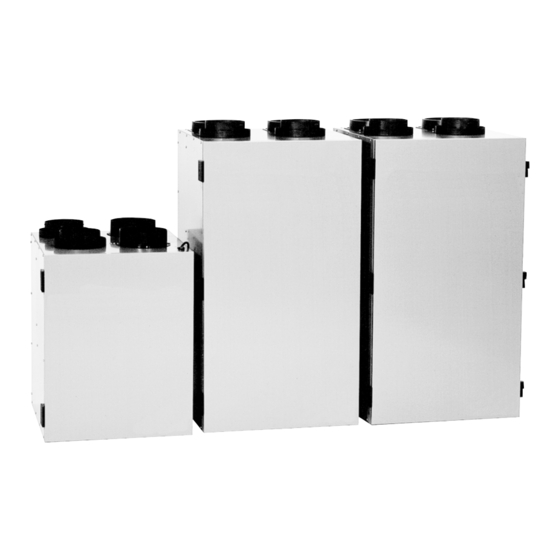
2.0 Service 2.1 3D Drawing for Venmar 1.3 HE, Venmar 3055 Compact, Venmar 5585 Compact and vänEE 1000 HE 18 19 VL0005... -
Page 5: Part Ordering Chart For Venmar 1.3 He,Venmar 3055 Compact, Venmar 5585 Compact And Vänee 1000 He
2.0 Service (cont’d) 2.2 Parts Ordering Chart for Venmar 1.3 HE, Venmar 3055 Compact, Venmar 5585 Compact and vänEE 1000 HE Description Venmar Venmar Venmar vänEE 1.3 HE 3055 Compact 5585 Compact 1000 HE Double Collar 6” 02021 02021 02021 02021 Single Collar 6”... -
Page 6: Drawing For Venmar 1.8 He, Venmar 2.6 He, Vänee 2000 He & Vänee 3000 He
2.0 Service (cont’d) 2.3 3D Drawing for Venmar 1.8 HE, Venmar 2.6 HE, vänEE 2000 HE and vänEE 3000 HE VL0006... -
Page 7: Part Ordering Chart For Venmar 1.8 He, Venmar 2.6 He, Vänee 2000 He & Vänee 3000 He
2.0 Service (cont’d) 2.4 Parts Ordering Chart for Venmar 1.8 HE, Venmar 2.6 HE, vänEE 2000 HE and vänEE 3000 HE Description Venmar Venmar vänEE vänEE 1.8 HE 2.6 HE 2000 HE 3000 HE Simple Collar 8” 01657 01657 01657 01657 Double Collar 6”... -
Page 8: Technical Data
3.0 Technical Data 3.1 Diagrams of Air Flows The direction of the air flow is indicated in each of the following diagrams (Figures 1 and 2). Please note that the stale air never mixes with the fresh air. FRESH AIR STALE AIR TO BUILDING FROM BUILDING... -
Page 9: Performance Charts
3.0 Technical Data (cont’d) 3.2 Performance Charts Models numbers: Venmar 1.3 HE and vänEE 1000 HE Electrical requirements: 120 volts, 1.2 Amps Exhaust Air Transfer Ratio: 0.02 VENTILATION PERFORMANCE External Static Net Supply Gross Air Flow Pressure Air Flow Supply... - Page 10 3.0 Technical Data (cont’d) 3.2 Performance Charts (cont’d) Model number: Venmar 5585 Compact Electrical requirements: 120 volts, 1.75 Amps Exhaust Air Transfer Ratio: 0.01 VENTILATION PERFORMANCE EXHAUST External Static Net Supply Gross Air Flow Pressure Air Flow Supply Exhaust in. w.g.
- Page 11 3.0 Technical Data (cont’d) 3.2 Performance Charts (cont’d) Model numbers: Venmar 2.6 HE and vänEE 3000 HE Electrical requirements: 120 volts, 5.4 Amps Exhaust Air Transfer Ratio: 0.02 • • VENTILATION PERFORMANCE* • • SUPPL Y • • External Static...
-
Page 12: Dimensions
3.0 Technical Data (cont’d) 3.3 Dimensions Model number: Venmar 3055 Compact Model numbers: Venmar 1.8 & 2.6 HE, 53,3 cm vanEE 2000 HE, (21'') vanEE 3000 HE 68,6 cm 47 cm (27'') (18-1/2'') 108,5 cm VK0020 (42-3/4") Model numbers: Venmar 5585 Compact, 58 cm vänEE 1000 HE... -
Page 13: Typical Installations
4.0 Typical Installations 4.1 Fully Ducted System (Primarily for homes with radiant hot water or electric baseboard heating. See Figure 4.) Moist, stale air is exhausted from the high humidity areas in the home, such as bathrooms, kitchens and laundry rooms. Fresh air is supplied to bedrooms and principal living areas. -
Page 14: Installation
5.0 Installation Inspect the Contents of the Box • Inspect the exterior of the unit for shipping damage. Ensure that there is no damage to the door, door latches, door hinges, dampers, duct collars, cabinet, etc. • Inspect the interior of the unit for damage. Ensure that the fan motor assembly, recovery core, insulation, damper, damper actuator and drain pan are all intact. -
Page 15: Installing Ductwork And Registers
5.0 Installation (cont’d) 5.3 Calculating Duct Size (cont’d) 5.3.1 Example for calculation: branches Problem: My installation requires two exhaust registers (one for the kitchen, one for the bathroom). I will connect these registers to a main duct connected to the unit (high speed 5”Ø... - Page 16 5.0 Installation (cont’d) 5.4 Installing Ductwork and Registers (cont’d) 5.4.2 Exhaust Ducted System (Source Point Ventilation) (see illustration, section 4.2) Stale air exhaust ductwork: (same as for Fully Ducted System, section 5.4.1) Fresh air distribution: WARNING When performing duct connection to the furnace, installation must be done in accordance with all applicable codes and standards.
- Page 17 5.0 Installation (cont’d) 5.4 Installing Ductwork and Registers (cont’d) 5.4.3 Simplified installation (Volume Ventilation) (see illustration, section 4.3) WARNING When performing duct connection to the furnace, installation must be done in accordance with all applicable codes and standards. Please refer to your local building code. CAUTION When performing duct connection to the furnace ducts (Method 1), these ducts must be sized to support the additional airflow produced by the HRV.
-
Page 18: Connecting Flexible Duct To The Unit
5.5 Connecting Flexible Duct to the Unit 5.5.1 For models Venmar 3055 Compact, 5585 Compact, vänEE 1000 HE, vänEE 2000 HE, Venmar 1.3 HE and Venmar 1.8 HE Use the following procedure for connecting the insulated flexible duct to the ports on the unit (exhaust to outside and fresh air from outside). -
Page 19: Installing Exterior Hoods
5.0 Installation (cont’d) 5.6 Installing Exterior Hoods Choose an appropriate location for installing the exterior hoods: • At a distance of at least 6 feet (1.8 m) one from the other • At a distance of 18 inches (457 mm) from the ground Make sure the intake hood is at least 6 feet (1.8 m) away from any of the following: •... -
Page 20: Connecting The Drain
5.0 Installation (cont’d) 5.7 Connecting the Drain 12"(305 mm) VO0004 VO0005 VO0003 Cut 2 sections of plastic tubing, about Join these 2 short sections to the“T” Attach the 2 plastic drain fittings to the unit using the gaskets, washers and 12”... -
Page 21: Electrical Connection To The Furnace
6.0 Installation of the Main Control (cont’d) 6.1 Installation (cont’d) 4- Connect the wires to the main control. (See Figure 17.) VD0026 5- Reinstall cover plate and buttons. Figure 17 6- Connect the wires to their corresponding positions inside the unit. Make sure the connection at the unit and at the wall control correspond exactly. -
Page 22: Wiring Diagram
1- F F Y WITH VENMAR 1.8 & 2.6 HE LINE VOLT L L AGE AND WITH vänEE 2000 & 3000 HE. 2- DAMPER MOTOR 2 IS USED ONLY WITH VENMAR 1.8 AND AND FIELD ä 3- FACTOR COLOR INSTEAD OF LOW SPEED. DISCONNECT RED WIRE FROM... -
Page 23: Air Flow Balancing
VP0007A Figure 20 NOTE: To get the best ventilation performance from Venmar 2.6 HE and vänEE 3000 HE, refer to Point 5.5.2 on page 17. Installation of Flow Collars Insert the flow collars in the duct at each location (A and B on Figure 20). Make sure their arrows are pointing in the direction of the airflow. -
Page 24: Maintenance
7.0 Air Flow Balancing (cont’d) Balancing procedure (cont’d) 4. Move tubing to the other side of the unit (location B in Figure 20 on page 21) and note reading. Adjust the fresh air balancing damper F until the reading at B is approximately the same as the reading at A. -
Page 25: Troubleshooting
9.0 Troubleshooting NOTE: Inspect the unit before proceeding with these steps. Start-up troubleshooting: Problems Possible causes You should try this 1. Unit does not work. • The circuit board may • Unplug the unit. Disconnect the be defective. main control and the optional(s) control(s) (if need be). -
Page 26: References
9.0 Troubleshooting (cont’d) Problems Possible causes You should try this 5. The defrost cycle • Ice deposits may be hindering • Remove the ice. does not work the damper operation. (the fresh air duct is frozen OR the fresh air •...
Need help?
Do you have a question about the 1.3 HE and is the answer not in the manual?
Questions and answers