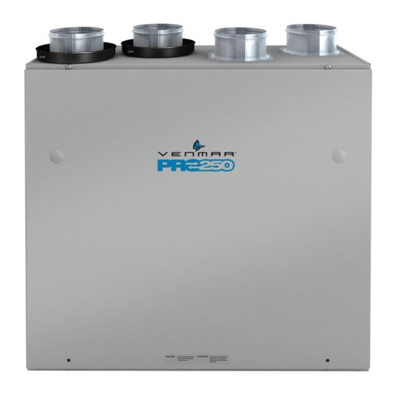
Heat recovery ventilators and
energy recovery ventilators (10 pages)
Summary of Contents for Venmar PRO225
Page 1
Installation and User Manual VB0121 PRO225 & PRO250 ECOVERY ENTILATORS READ AND SAVE THESE INSTRUCTIONS Venmar Ventilation inc., 550 Lemire Blvd., Drummondville, QC, Canada J2C 7W9 www.venmar.ca These products earned ENERGY STAR ® by meeting strict energy efficiency guidelines set by Natural Resources Canada and the US EPA.
Page 2
7. Do not use these units with any solid-state speed control devices other than the Breeze main control for the PRO250 unit exclusively or the 11136 main control for PRO225 unit. The optional auxiliary control 20-minute lighted push button can be used with both PRO250 and PRO225 units.
5.3 Main Control Installation................16 6. O ............17-18 PERATING ONTROLS 6.1 Breeze Main Control (PRO250 only) ............17 6.2 11136 Main Control (PRO225 only)............18 6.3 20-minute Lighted Push Button Optional Auxiliary Control (PRO250 & PRO225)..................18 7. M ................19 AINTENANCE 7.1 Regular Maintenance ................19 7.2 Annual Maintenance .................19...
These units also come equipped with a heat recovery core which reduces ventilating costs in winter. The PRO250 and PRO225 Heat Recovery Ventilators are ventilation systems which carry out the following operations: 1.1 A (PRO250 &...
2. DIAGRAMS OF AIRFLOWS The direction of the airflows is indicated in each of the following diagrams. Please note that the stale air never mixes with the fresh air. TALE AIR RESH AIR TALE AIR RESH AIR TO OUTSIDE FROM OUTSIDE FROM BUILDING TO BUILDING URING...
3. DESCRIPTION OF THE UNIT VL0035 1 Exhaust port: exhausts stale air to the outside, after the air has transferred its heat inside the heat recovery core. 2 Fresh air port: brings fresh air from the outside into the unit. 3 Stale air intake port: is connected to the registers located in the larger rooms of the house.
4. UNIT INSTALLATION 4.1 I NSTALLATION YPES WITH EQUIRED NSTALLATION Here are the types of installation and installation kit needed depending on your house. BUNGALOW BUNGALOW • L • L ATERAL STAIRWAY ATERAL OR CENTRAL STAIRWAY • O • C PEN BASEMENT STAIRWELL LOSED IN BASEMENT STAIRWELL...
4. UNIT INSTALLATION (CONT’D) 4.2 L OCATING AND OUNTING THE Choose an appropriate location for the unit: • Within a heated area of the house (10 °C/50 °F or more) • Away from living areas (dining room, living room, bedrooms), if possible •...
4. UNIT INSTALLATION (CONT’D) 4.5 P LANNING OF THE UCTWORK • Keep it simple. Plan for a minimum of bends and joints. Keep the length of the insulated ducts to a minimum. • Do not use wall cavities as ducts. Do not use branch line smaller than 4” (102 mm) diameter.
4. UNIT INSTALLATION (CONT’D) 4.6 I ’ NSTALLING NSULATED LEXIBLE UCTS AND EGISTERS CONT 4.6.4 C ONNECTION TO A ORCED YSTEM A. F RESH AIR TO BUILDING DUCT ONLY WARNING When performing duct connections, always use approved tools and materials. Respect all corresponding laws and safety regulations. Please refer to your local building code.
4. UNIT INSTALLATION (CONT’D) 4.6.5 H OW TO ONNECT NSULATED LEXIBLE UCTS TO THE ORTS • Each port is identified on top of the unit (see illustrations below). Attach the fresh air to building duct and the exhaust air from building duct to their corresponding port, using tie wraps (1).
4. UNIT INSTALLATION (CONT’D) 4.8 L OCATING XTERIOR ORTS Choose an appropriate location for installing the exterior ports: • At a distance of at least 6 feet (1.8 m) one from the other • At a minimum distance of 18 inches (457 mm) from the ground WARNING Make sure the fresh air intake port is at least 6 feet (1.8 m) away (or more, as per applicable building codes or standards) from sources of contamination such as:...
4. UNIT INSTALLATION (CONT’D) 4.10 C ONNECTING THE DRAIN Cut 2 sections of the plastic tube, at least 16” (406 mm) long, and attach them to each inner drain fitting, located under the unit. Join both 16" 16" short sections to the “T” junction and main tube (406 mm) (406 mm) as shown.
5. CONTROLS (CONT’D) 5.1 I ’ NTEGRATED ONTROL CONT If a problem occurs during the unit operation, its integrated control LED (2) will blink. The color of the blinking light depends on the type of error detected. Refer to Section 8 Troubleshooting on page 20 for further details.
Page 15
5. CONTROLS (CONT’D) 5.2 C ’ ONTROLS ONNECTION TO THE CONT 5.2.2 11136 M (PRO225 ONTROL ONLY NO C NC I OC OL Y R G B %HUM. RELATIVE HUM EXT. TEMPS. ° C EXT. 10 ° 0° 5˚C+ -10 °...
(CONT’D) 5.3 M ONTROLS NSTALLATION For more convenience, the PRO250 and PRO225 units can also be controlled using the included main controls: the Breeze main control for the PRO250 unit and the 11136 main control for the PRO225 unit. WARNING Always disconnect the unit before making any connections.
6. OPERATING CONTROLS 6.1 B (PRO250 REEZE ONTROL ONLY NOTE: The integrated control must be turned OFF to use this control. XCHANGE UTOMATIC NDICATOR NDICATOR AUTO UMIDITY INIMUM PEED ÉCHANGE ONTROL EXCHANGE MIN. NDICATOR XCESS HUMIDITY EXCÈS D’HUMIDITÉ ECIRCULATION RE-CIRC EXCESS HUMIDITY NDICATOR NDICATOR...
IGHTED UTTON PTIONAL UXILIARY ONTROL (PRO250 & PRO225) Location: Located in the bathroom or in other locations where there is temporary humidity excess or pollutants. Purpose: To eliminate excess humidity produced by showers or other periodic activities producing pollutants. NOTE: This control is sold separately.
7. MAINTENANCE WARNING Dangerous voltage may be present. During maintenance and repairs, the unit must always be turned off, then unplugged. We take great care to minimize sharp edges; however, please proceed with caution when handling all components. When cleaning the unit, it is recommended to wear safety glasses and gloves.
- Do not adjust your humidity control below -20°C (-4°F). - Set the unit at minimum speed (MIN.). - Temporarily switch to the AUTOMATIC mode. • PRO225 unit only (with 11136 control) - Set the Humidity level selector below 30% (see 6.2 on page 18).
Page 21
Ventilation ULC warrants to the original purchaser of its products, that such products will be free from defects for the period stated below, from date of original purchase. For this Venmar unit, the warranty covers parts only against any operational defect. This is a a 2-year warranty. Subject to perform the core maintenance according to user guide recommendations, the heat recovery core (HRV) has a limited lifetime warranty.
Need help?
Do you have a question about the PRO225 and is the answer not in the manual?
Questions and answers