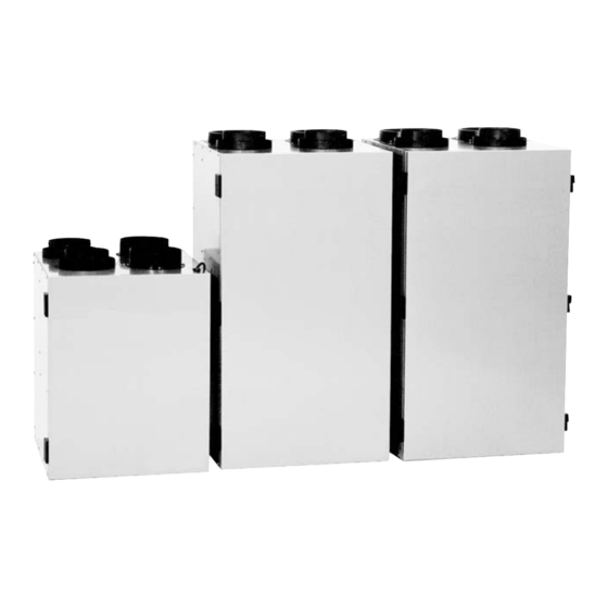
Venmar 3055 Compact User Manual

Venmar 3055 Compact User Manual

Heat recovery ventilators
Hide thumbs Also See for 3055 Compact:

Advertisement

Read and save these instructions.
H
EAT
1000 HE
2000 HE
3000 HE
3055 Compact
VB0021
User Manual
R
ECOVERY
MODELS
VVI, 550 Lemire Blvd., Drummondville, Qc, Canada
V
ENTILATORS
:
HE 1.3
HE 1.8
HE 2.6
5585 Compact
J2C 7W9
09/2004
#02053

Advertisement

Table of Contents
loading
Need help?

Need help?

Do you have a question about the 3055 Compact and is the answer not in the manual?

Questions and answers

Summary of Contents for Venmar 3055 Compact

  • Page 1 User Manual Read and save these instructions. ECOVERY ENTILATORS MODELS 1000 HE HE 1.3 2000 HE HE 1.8 3000 HE HE 2.6 3055 Compact 5585 Compact VB0021 VVI, 550 Lemire Blvd., Drummondville, Qc, Canada J2C 7W9 09/2004 #02053...
  • Page 2 Congratulations! You have made an excellent choice! The operating principle of your Heat Recovery Ventilator will protect your house and give you personnal comfort you have never known before. We have prepared this Operating Guide especially for you. Please read it carefully to ensure you obtain full benefit from your Heat Recovery Ventilator unit.
  • Page 3: Table Of Contents

    Table of contents Functions of your HRV ......1 1.1 Air Exchange ......... . . 1 1.2 Heat Recovery .
  • Page 4: Functions Of Your Hrv

    The unit exhausts stale and humid air from the house and replaces it with fresh air from the outside. MODELS RATES 1000 HE / HE 1.3 / 3055 Compact 30 to 60 l/s (65 to 130 cfm) 2000 HE/ HE 1.8 55 to 93 l/s (115 to 197 cfm)
  • Page 5: Circulation

    FROM BUILDING SIDE 0°C/32°F 22°C/72°F VF0026 1000 HE, HE 1.3, 3055 Compact, 5585 Compact 1.3 Circulation (available with ULTIMA control only) During the circulation mode, when the selected level of humidity is reached, the unit stops to exchange air with the exterior. Continuous circulation is thus undertaken inside the home and insures the purification of the ambiant air.
  • Page 6: Diagrams Of Air Flows

    The direction of the air flow is indicated in each of the following diagrams. Please note that the stale air never mixes with the fresh air. MODELS 1000 HE, HE 1.3, 3055 Compact, 5585 Compact FRESH AIR FRESH AIR TO BUILDING...
  • Page 7 2.0 Diagrams of Air Flows (cont’d) MODELS 2000 HE, 3000 HE, HE 1.8, HE 2.6 FRESH AIR STALE AIR during TO BUILDING FROM BUILDING air exchange STALE AIR FRESH AIR TO OUTSIDE FROM OUTSIDE VF0025 during circulation FILTERED AIR STALE AIR TO BUILDING FROM BUILDING and defrost...
  • Page 8: Description Of Unit

    3.0 Description of the Unit 1) Stale air intake port: is connected to the registers located in the larger rooms of the house. 2) Fresh air port: brings fresh air from the outside into the unit. 3) Exhaust port: exhausts stale air to the outside, after the air has transferred its heat inside the heat recovery core.
  • Page 9 3.0 Description of the Unit (cont’d) MODELS 1000 HE, HE 1.3, 3055 Compact, 5585 Compact VL0003 MODELS 2000 HE, 3000 HE, HE 1.8, HE 2.6 VL0012...
  • Page 10: Operating The Wall Control

    4.0 Operating the Wall Controls The following illustrations show the main controls. Refer to next pages for operating instructions. 1000 HE HE 1.3, HE 1.8, HE 2.6 2000 HE 3585 Compact 3000 HE 5585 Compact CONDENSATI0N CONTROL -20°C ° -4°F 41°F AIR SUPPLY CONTROL MIN.
  • Page 11: Basic And Venta Controls

    4.0 Operating the Wall Controls (cont’d) 4.1 Basic and Venta Controls Purpose: To adjust air supply and select desired indoor humidity level. AIR SUPPLY CONTROL DJUSTING 1) Select speed “MIN.” or “MAX.” using slide switch. • When “MIN.” (minimum speed) is selected, if the knob is set above the click, the unit will exchange in low speed with the outside and if it is set below the click, the unit will exchange on high speed with the outside until the desired humidity level has been reached.
  • Page 12: Electro And Supra Controls

    4.0 Operating the Wall Controls (cont’d) 4.2 Electro and Supra Controls Purpose: To adjust air supply and select desired indoor humidity level. AIR SUPPLY CONTROL DJUSTING 1) Select speed “MIN.”, “MAX.” or INTERMITTENT using the push button. • When “MIN.” (minimum speed) is selected, if the knob is set above the click, the unit will exchange in low speed with the outside and if it is set below the click, the unit will exchange on high speed with the outside until the desired humidity level has been reached.
  • Page 13: Ultima Control

    4.0 Operating the Wall Controls (cont’d) 4.4 Ultima Control Purpose: To adjust air supply and select desired indoor humidity level. AIR SUPPLY CONTROL DJUSTING 1) Select speed “MIN.”, “MAX.” or INTERMITTENT using the push button. • When “MIN.” (minimum speed) is selected, if the knob is set above the click, the unit will exchange in low speed with the outside and if it is set below the click, the unit will exchange on high speed with the outside until the desired humidity level has been reached.
  • Page 14: Maintenance

    5.0 Maintenance WARNING Risk of electric shock. Before performing any maintenance or servicing, always disconnect the unit from its power source. 5.1 Regular Maintenance ) The motors are factory lubricated for life. Lubricating the bearings is not recommended. CAUTION Because the unit is suspended, two people are recommended to remove or install the heat recovery core.
  • Page 15: Annual Maintenance

    5.0 Maintenance (cont’d) 5.2 Annual Maintenance NOTE: Ask your installer for an annual service contract. Annual service should include: 1) Cleaning filters, heat recovery core and the exterior air intake/exhaust hood. 2) Cleaning the wheels and the blower blades. 3) Cleaning the condensation tray with soapy water (make sure that the drain is not clogged).
  • Page 16: Troubleshooting

    6.0 Troubleshooting TYPES OF PROBLEM TRY THIS... Nothing works. • Check if the unit is plugged in. • Check if the unit is receiving power from the house circuit breaker. Condensation on windows. • Adjust the humidity control knob as per instructions (see Section 4). •...

Table of Contents

Save PDF