Table of Contents
Advertisement
Advertisement
Table of Contents

Subscribe to Our Youtube Channel
Related Manuals for Venmar ERV500i


Summary of Contents for Venmar ERV500i
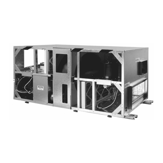
- Page 1 Installation, Operation and Maintenance Instructions ERV500i/e ERV500i...
-
Page 2: Table Of Contents
Table Of Contents Safety Considerations ..............3 General Information . -
Page 3: Safety Considerations
ERV500i and ERV500e at the base of the unit. Hole centers are shown in the The ERV500i ventilator is intended for installation with- overall dimensional drawings in Appendix B. Rubber or in a suspended ceiling space or mechanical room. The... -
Page 4: Make Duct Connections
Make Duct Connections CAUTION All panels must be in place when rigging. ERV500i Port locations for the indoor unit are labeled in Spreader bars are required to prevent damage to the Appendix B-1. roof flange. Rollers may be used to move the unit across An 18"... -
Page 5: Systems Integration
All field wiring must comply with NEC and local require- ments. In Canada, electrical connections must be in accordance with CSA C22.1 Canadian Electrical Code 48644 POWER CONTROL BOARD Part One. ERV500i ERV500e Line Voltage 11.1 Field Connection A high voltage connection (shown below) is located on the outside of the unit with knockout. -
Page 6: Start Up
A low voltage remote control wiring interface is provided on the unit. The installer must provide wiring for the con- Recirculation (ERV500i ONLY) trols that may be supplied optionally. The optional wall The exhaust fan is de-energized. There is no outdoor controls require a 4-wire LVT 24 gauge (or equivalent). -
Page 7: Airflow Balancing
See Appendix G for airflow perfor- mance charts. Set the dampers to establish the minimum duct pressure required. Further adjust the dampers to reduce flow to the desired, balanced rate. Rotor Brush Seal ERV500i/e ROTOR 18" Dia. 8" Depth Press. drop in W. G. 0.45 0.60... -
Page 8: Motor And Blower Removal
Motor And Blower Removal Supply After disconnecting the power from the unit, disconnect WARNING the 3-wire connector between the supply motor and control box. Disconnect the main power switch to the unit before performing service and maintenance procedures. Exhaust After disconnecting the power from the unit, disconnect all the plug-in connectors on the left side of the control box. -
Page 9: Cassette Service
Remove the cassette assembly by sliding it forward out of the cassette guides. Ensure that no wires are damaged during this process. Using a 1/8" Allen key, loosen the two set screws used to tighten the cassette bearing to the cassette shaft. The set screws are located in-line with the cassette shaft, between the cassette and the cassette beam. - Page 10 Remove the outer half of the adjustable sheave (pulley). Using a 5/32" Allen key, loosen the set screw located on the outer half of the adjustable sheave. Remove the outer half of the adjustable sheave by turning it counter-clockwise. This sheave piece is threaded and therefore it will take a few rotations to completely remove it.
-
Page 11: Appendix A: Roofcurb Detail
Appendix A Roofcurb Detail (ERV500e ONLY) ERV500e - 11 -... -
Page 12: Appendix B: Dimensional Drawing
Appendix B Dimensional Drawing B-1: ERV500i - 12 -... - Page 13 Appendix B Continued Dimensional Drawing B-2: ERV500e - 13 -...
-
Page 14: Appendix C: Hood Installation And Rigging
Appendix C Hood Installation And Rigging (ERV500e ONLY) Hood Installation Detail "A" See Detail "A" Screw: #10 x 3/4 Detail "B" See Detail "B" Black Female Male Female Male Black White White Rigging SPREADER BARS NOTE: Remove all packaging before beginning to rig the unit onto the installed roofcurb. -
Page 15: Appendix D: Minimum Distance Requirements And Typical Installation
Appendix D Minimum Distance Requirements And Typical Installation D-1: ERV500i - Minimum Distance Requirements Flow Measuring Exhaust Air Min. 36" Station (FMS) Balancing From Space [914mm] Damper Flexible Duct Connection Supply Air To Space Exhaust Air Min. 36" To Outside [914mm] Min. -
Page 16: Appendix E: Components
Appendix E Components ERV500i Item Description Supply blower Supply blower motor Exhaust blower Exhaust blower motor Control box Supply filter Exhaust filter Damper actuator Intake damper Enthalpy wheel Wiper seal NOTE: Some unit components listed above are optional. Consult the unit nomenclature for standard and optional components. - Page 17 Appendix E Continued Components ERV500e 10 14 4 Item Description Housing Fan motor Enthalpy wheel Wheel drive motor Wheel drive pulley Wheel drive belt Wheel perimeter seal Wheel wiper seal Damper actuator Damper intake Exhaust damper actuator Exhaust damper MEF supply filter set - 2/set MEF exhaust filter set - 2/set Oudoor air intake hood Exhaust air hood...
-
Page 18: Appendix F Equipment Data
Appendix F Equipment Data ERV500i ERV500e Rated airflow (cfm) 620 cfm @ 0.50" w.g. 500 cfm @ 0.50" w.g. Shipping weight 320 lbs [145 kg] 320 lbs [145 kg] Shipping dimensions 57.5" x 24.75" x 24" 68" x 27" x 23"... -
Page 19: Appendix H: Terminal Control Diagrams
Appendix H Terminal Control Diagrams H-1: Wall Control Connection H-2: Occupied Timer/Sensor Connection Two types of remote wall controls are available: Occupancy control is achieved by connection to the ter- minal interface shown below. These terminals require a 1. Standard Wall Control with fan switch and dehu- dry contact which could be provided by a number of types midistat control. - Page 20 Appendix H Continued Terminal Control Diagrams H-3: Enthalpy Control H-4: Remote Fan Control Energy Recovery Ventilators (ERVs) can be controlled Remote fan control can be achieved by connecting dry by an enthalpy controller that switches between free cool- contact controls to the terminal interface at terminals ing and A/C unit cooling.
- Page 21 Appendix H Continued Terminal Control Diagrams H-5: Low Temperature Control The fans of the ERV can be controlled using a setpoint low temperature controller. If the supply air discharge tem- CONTROL CONTACTS NOTE: perature falls below the setpoint on the low temperature BLACK GREEN 1) R - W breaks on temperature fall...
- Page 22 CONDITION TO PANEL. 2 ALARM (+) ALARM SIGNAL TROUBLE CONTACT RATING H-8: Unoccupied Recirc Contacts 0.3A @ 32 VAC/DC (ERV500i ONLY) 1 COMMON (D) AUX POWER TROUBLE CONTACTS CLOSED IN STANDBY FIELD (+) AUX POWER AND ALARM. CONTACTS OPEN WHILE...
-
Page 23: Appendix I Trouble Shooting
Appendix I Trouble Shooting Problem Cause Solution Unit will not turn on. External wiring not connected. Check external wiring. Internal wiring not making contact. Check the wiring in the control box. Occ./Unocc. control circuit is open. Close circuit. Unit will not turn off. External terminal strip wiring. - Page 24 Venmar CES Inc. Venmar CES products are licensed to use the following label of approval: Saskatoon, SK Canada www.venmarces.com © 1999 • PN 204279 • 06/2010...
Need help?
Do you have a question about the ERV500i and is the answer not in the manual?
Questions and answers