Table of Contents
Advertisement
VB0205
VB0206
USER AND INSTALLER MANUAL
!
RESIDENTIAL USE ONLY
READ AND SAVE THESE INSTRUCTIONS
These products earned the ENERGY STAR
meeting strict energy efficiency guidelines set by
Natural Resources Canada and the US EPA. They
meet ENERGY STAR requirements only when used
in Canada.
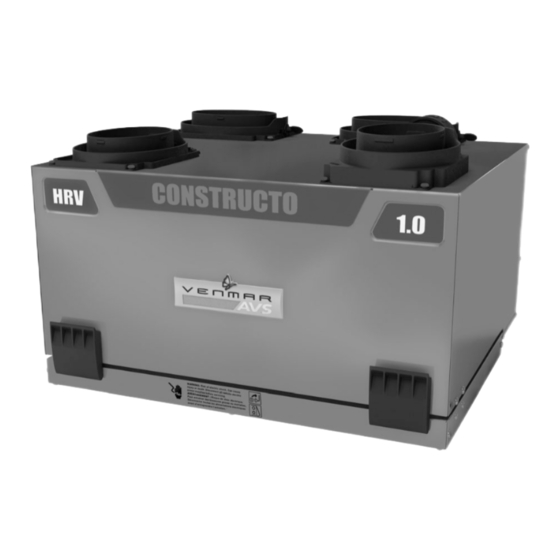
TOP PORTS UNITS
Constructo 1.0
C12
60H
60H+
SIDE PORTS UNITS
Constructo 1.0
C12
60H
60H+
!
1
HRV
ERV
41502
41506
41552
41556
41602
41606
41652
41656
HRV
ERV
41500
41504
41550
41554
41600
41604
41650
41654
®
by
21784 rev. 09
Advertisement
Table of Contents
Troubleshooting


Need help?
Do you have a question about the 41502 and is the answer not in the manual?
Questions and answers