Advertisement
Quick Links
www.freeservicemanuals.info
SERVICE MANUAL
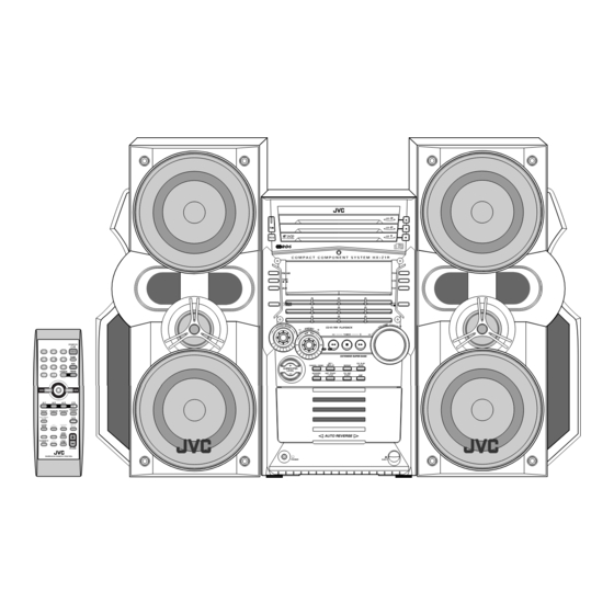
COMPACT COMPONENT SYSTEM
Contents
Safety precautions
Preventing static electricity
Important for laser products
Disassembly method
Adjustment method
HX-Z1R
1-2
Flow of functional operation
1-4
1-5
Maintenance of laser pickup
1-6
Replacement of laser pickup
1-24
Description of major ICs
Digitized in Heiloo Netherlands
COPYRIGHT
2002 VICTOR COMPANY OF JAPAN, LTD.
COMPACT
DIGITAL AUDIO
until TOC read (CD)
3/29/2018
HX-Z1R
HX-Z1R
Area Suffix
B ----------------------- U.K.
E-------- Continental Europe
EN----------Northern Europe
EV------------Eastern Europe
1-29
1-30
1-30
1-31~41
No.21114
Jul. 2002
1-1
Advertisement

Related Manuals for JVC HX-Z1R


Summary of Contents for JVC HX-Z1R
- Page 1 3/29/2018 HX-Z1R HX-Z1R SERVICE MANUAL COMPACT COMPONENT SYSTEM HX-Z1R COMPACT DIGITAL AUDIO Area Suffix B ----------------------- U.K. E-------- Continental Europe EN----------Northern Europe EV------------Eastern Europe Contents Safety precautions Flow of functional operation Preventing static electricity until TOC read (CD) 1-29...
- Page 2 3/29/2018 HX-Z1R 1. This design of this product contains special hardware and many circuits and components specially for safety purposes. For continued protection, no changes should be made to the original design unless authorized in writing by the manufacturer. Replacement parts must be identical to those used in the original circuits. Services should be performed by qualified personnel only.
- Page 3 3/29/2018 HX-Z1R (U.K only) 1. This design of this product contains special hardware and many circuits and components specially for safety purposes. For continued protection, no changes should be made to the original design unless authorized in writing by the manufacturer.
- Page 4 3/29/2018 HX-Z1R Preventing static electricity 1. Grounding to prevent damage by static electricity Electrostatic discharge (ESD), which occurs when static electricity stored in the body, fabric, etc. is discharged, can destroy the laser diode in the traverse unit (optical pickup). Take care to prevent this when performing repairs.
- Page 5 3/29/2018 HX-Z1R Important for laser products 5.CAUTION : If safety switches malfunction, the laser is able 1.CLASS 1 LASER PRODUCT to function. 2.DANGER : Invisible laser radiation when open and inter 6.CAUTION : Use of controls, adjustments or performance of lock failed or defeated.
- Page 6 3/29/2018 HX-Z1R Disassembly method Metal cover <Main board> Removing the metal cover (See Fig.1 ~ 3) Remove the six screws A on the back of the body. Remove the screw B on each side of the body. Remove the metal cover from the body by lifting the rear part of the cover.
- Page 7 3/29/2018 HX-Z1R Front panel assembly Removing the front panel assembly (See Fig.6 ~ 9) Bridge board CN701 Prior to performing the following procedure, remove the metal cover and the CD changer mechanism assembly. Disconnect the card wire from connector CN44 and...
- Page 8 3/29/2018 HX-Z1R Removing the antenna board (See Fig.10, 11) Antenna board Rear panel Prior to performing the following procedure, remove the metal cover. REFERENCE: There is no need to remove the CD changer mechanism assembly. Disconnect the card wire from connector CN1 on the antenna board on the right side of the body.
- Page 9 3/29/2018 HX-Z1R Removing the rear panel Tie band Inner bar (See Fig.12 ~ 17) Prior to performing the following procedure, remove Joint b the metal cover and the CD changer mechanism assembly. Remove holding board by remove two plastic rivets and then slide out the holding board as shown in fig.
- Page 10 3/29/2018 HX-Z1R Removing the fan assembly (See Fig.18, 19) Prior to performing the following procedure, remove the metal cover and the CD changer mechanism assembly and the rear panel. Remove two screws G on the rear panel. Rotate fan assembly in clockwise direction to release fan assembly from rear panel (joint d).
- Page 11 3/29/2018 HX-Z1R Removing the bridge board / regulator Plastic rivet board / heat sink (See Fig.21 ~ 27) Prior to performing the following procedure, remove the metal cover, the CD changer mechanism assembly, the rear panel, the antenna board and Inner bar main board.
- Page 12 3/29/2018 HX-Z1R Remove the two screws J attaching the heat sink bracket. Bridge board Remove the two screws M, detach bridge board from regulator board by disconnect connector CN205. Remove the screws K and L to detach regulator board from heat sink.
- Page 13 3/29/2018 HX-Z1R Removing power transformer assembly (See Fig.28, 29) Prior to performing the following procedure, remove Power transformer assembly the metal cover, the CD changer mechanism assembly, the rear panel, the main board and the bridge board / regulator board.
- Page 14 3/29/2018 HX-Z1R Removing the display system control board (See Fig.31, 32) Remove the four screws S attaching the stay bracket (1). Disconnect the card wire from connector CN43 and Display system CN880 on the display system control board. Stay bracket (1)
- Page 15 3/29/2018 HX-Z1R Removing the CD Servo control board (See Fig.1) 1.Remove the metal cover. 2.Remove the CD changer mechanism assembly. 3.From bottom side the CD changer mechanism assembly, remove the four screws A retaining the CD servo control CN854 board.
- Page 16 3/29/2018 HX-Z1R Stopper Check whether the lifter unit stopper has been caught into the hole at the section "e" of CD tray assembly as shown in Fig.5. Make sure that the driver unit elevator is positioned as shown in Fig.6 from to the second or fifth hole on the left side face of the CD changer mechanism assembly.
- Page 17 3/29/2018 HX-Z1R Cams R1, R2 assembly Removing the CD loading mechanism assembly(See Fig.10) While turning the cams R1 and R2 assembly in the arrow direction "h" ,align the shaft "i" of the CD loading mechanism assembly to the position shown in Fig.10.
- Page 18 3/29/2018 HX-Z1R Removing the try select switch board Chassis assembly (See Fig.14) Remove the two screws G retaining the tray select switch board. Tray select switch board Disconnect the tray select switch board from connector CN804 on the CD servo control board.
- Page 19 3/29/2018 HX-Z1R Removing the actuator motor and belt Gear bracket (See Fig.18~21) Remove the two screws I retaining the gear bracket (See Fig.18). While pressing the pawl "t" fixing the gear bracket in the arrow direction, remove the gear bracket Pulley gear (See Fig.18).
- Page 20 3/29/2018 HX-Z1R Removing the cams R1/R2 assembly Slit washer and cam gear q(See Fig.22) Cam R2 Slit washer Remove the slit washer fixing the cams R1 and R2 assembly. Cam gear q By removing the two pawls "w" fixing the cam R1, separate R2 from R1.
- Page 21 3/29/2018 HX-Z1R <Cassette mechanism section> Cassette mechanism Removing the playback / recording & eraser head (See Fig. 1 ~ 3) While shifting the trigger arms seen on the right side of the head mount in the arrow direction, turn the...
- Page 22 3/29/2018 HX-Z1R Removing the head amplifier & mechanism control board (See Fig. 4) Belt Remove the cassette mechanism assembly. Main motor CN32 assembly After turning over th cassette mechanism assembly, remove the three screws A retaining the head amplifier & mechanism control board.
- Page 23 3/29/2018 HX-Z1R Removing the flywheel (See Fig. 7, 8) Remove the head amplifier & mechanism control P.C. board. Remove the main motor assembly. After turning over the cassette mechanism, remove Flywheel (R) Flywheel (L) the two slit washers and fixing the capstan shafts R and L, and pull out the flywheel (R) and (L) respectively from behind the cassette mechanism.
- Page 24 3/29/2018 HX-Z1R Adjustment method Measurement Instruments Required for Tuner section Adjustment FM Band cover: 87.5 108MHz 1. Low frequency oscillator MW Band cover: 522 1,629kHz This oscillator should have a capacity to output LW Band cover: 144 288kHz 0dBs to 600...
- Page 25 3/29/2018 HX-Z1R << >> Arrangement of Adjusting Position Cassette mechanism section Cassette mechanism section (Back side) Head azimuth Head azimuth adjusting screw adjusting screw (Forward side) (Reverse side) Head azimuth Head azimuth Playback/Recording & adjusting screw adjusting screw eraser head...
- Page 26 3/29/2018 HX-Z1R Tape Recorder Section Measurement Adjusting Standard Items Measurement method conditions positions Values Adjust the head Confirmation Test tape 1 Playback the test tape VTT703L (8kHz) Maximum azimuth screw of head angle : VTT703L (8kHz) 2 With the recording & playback mechanism,...
- Page 27 3/29/2018 HX-Z1R Electrical Performance Adjusting Measurement Standard Items Measurement method positions conditions Values VR31 AC-225 Adjustment of Mode: Forward or 1 With the recording and playback : 4.20 recording bias reverse mode mechanism, load the test tapes (AC-514 to...
- Page 28 3/29/2018 HX-Z1R Extension code connecting method Main board CN661 CD servo control board CN651 1-28 Digitized in Heiloo Netherlands...
- Page 29 3/29/2018 HX-Z1R Flow of functional operation until TOC read Check Point Slider turns REST Play Key Power ON Confirm that the voltage at the pin5 SW ON. of CN801 is "H"\"L"\"H". Automatic tuning of TE offset Check that the voltage at the...
- Page 30 3/29/2018 HX-Z1R Maintenance of laser pickup Replacement of laser pickup (1) Cleaning the pick up lens Before you replace the pick up, please try to Turn off the power switch and, disconnect the clean the lens with a alcohol soaked cotton power cord from the ac outlet.
- Page 31 3/29/2018 HX-Z1R Description of major ICs BU2092 (IC642) : Port expander 1.Pin Layout DATA CLOCK CONTROL CIRCUIT 2.Pin function Symbol Function Pin No. Connect to GND DATA Serial Data input CLOCK Shift Clock of Data Latch Clock of Data...
- Page 32 3/29/2018 HX-Z1R BH3874AKS (IC434) : Audio sound processor 1. Pin layout 2. Block diagram 63 64 3 4 7 8 11 12 -9dB FILTER INLD 0~30dB -30dB~- INLC 11dB INLB OUTL INLA 5 BAND EQ BASS5 19dB FILTER 5 BAND EQ...
- Page 33 3/29/2018 HX-Z1R 3. Pin function Pin NO. Name Function Pin NO. Name Function Serial data larch receiving pin F1R1 Rch GREQ f1 filter setting pin F1R2 Rch GREQ f1 filter setting pin Serial clook receiving pin Parallel data receiving pin...
- Page 34 3/29/2018 HX-Z1R KIA7805API (IC360) : Regulator 1. Pin layout 1.VCC 2.GND 3.OUTPUT 2.Block diagram INPUT Q11-1 OUTPUT COMMON (GND) 1-34 Digitized in Heiloo Netherlands...
- Page 35 3/29/2018 HX-Z1R KIA7808API (IC303) : Regulator 1. Pin layout 1.VCC 2.GND 3.OUTPUT 2.Block diagram INPUT Q11-1 OUTPUT COMMON (GND) 1-35 Digitized in Heiloo Netherlands...
- Page 36 3/29/2018 HX-Z1R KIA7812API (IC240) : Regulator 1. Pin layout 1.VCC 2.GND 3.OUTPUT 2.Block diagram INPUT Q11-1 OUTPUT COMMON (GND) 1-36 Digitized in Heiloo Netherlands...
- Page 37 3/29/2018 HX-Z1R KIA7042AP-T (IC830) : Regulator 2. Block diagram 1. Pin layout 1.VCC 2.GND 3.OUT NJM4580D (IC501, IC502, IC571) : LPF, Mic and H.phone amp. 1. Pin layout A OUT A -IN B OUT A +IN B -IN B +IN (TOP VIEW) 2.
- Page 38 3/29/2018 HX-Z1R GP1U271XK (IC951) : Receiver for remote – Limiter Integrator Comparator Amp. B.P.F Demodulator Vout STK402-050 (IC602) : 2ch AF power amp. Pin layout 2.Block diagra TR1E TR12 TR10 TR13 TR16 1-38 Digitized in Heiloo Netherlands...
- Page 39 3/29/2018 HX-Z1R STK402-010 (IC701) : 2ch AF power amp. 1. Pin layout 2.Block diagra TR41 18 17 Comparator TR12 TR11 TR16 TR19 R1 C1 TR14 TR13 TR18 TR20 TR10 TR15 TR17 Comparator TR51 9 8 11 10 1-39 Digitized in Heiloo Netherlands...
- Page 40 3/29/2018 HX-Z1R UPD784975AGF303 (IC810) : Main micon 1. Pin layout 2. Pin function Pin NO. Name Function Pin NO. Name Function AVDD AD VDD, same as VDD1 SPI A SPI A data SPI analog input SPI B SPI B data...
- Page 41 3/29/2018 HX-Z1R KIA7809API (IC305) : Regulator 1.Pin layout 1.INPUT 2.COMMON 3.OUTPUT 1 2 3 2.Block diagram INPUT Q11-1 OUTPUT COMMON (GND) 1-41 Digitized in Heiloo Netherlands...
- Page 42 3/29/2018 HX-Z1R HX-Z1R VICTOR COMPANY OF JAPAN, LIMITED AUDIO & COMUNICATION BUSINESS DIVISION PERSONAL & MOBILE NETWORK BUSINESS UNIT. 10-1,1chome,Ohwatari-machi,Maebashi-city,371-8543,Japan Printed in Japan 1-42 Digitized in Heiloo Netherlands (No.21114) 200207...
-
Page 43: Table Of Contents
3/29/2018 HX-Z1R PARTS LIST [ HX-Z1R ] * All printed circuit boards and its assemblies are not available as service parts. HX-Z1R Area suffix B ------------------------------- U.K. E ----------- Continental Europe EN ------------ Northern Europe EV -------------- Eastern Europe... - Page 44 3/29/2018 HX-Z1R < M E M O > Digitized in Heiloo Netherlands...
- Page 45 3/29/2018 HX-Z1R Exploded view of general assembly and parts list Block No. FL board CD servo board Speaker board Tuner board Switch board Main board Power amplifier board Headphone board Digitized in Heiloo Netherlands...
- Page 46 3/29/2018 HX-Z1R HX-Z1R Parts list (General assembly) Parts list (General assembly) Block No. M1MM Block No. M1MM Item Description Item Description Parts number Parts name Q'ty Area Parts number Parts name Q'ty Area GV10115-003A FRONT PANEL LV42763-002A INSULATOR GV40313-001A...
-
Page 47: Parts List
3/29/2018 HX-Z1R Parts list (General assembly) Block No. M1MM Item Parts number Parts name Q'ty Description Area GV40121-004A SPACER 3 STICK AT I.BAR LV30225-079A SPACER 1 STICK AT I.BAR GV40186-001A 1 AT VOL.KNOB QYSBSGG3008E T.SCREW 1 INNER BAR/FMH B... -
Page 48: Speaker Assembly And Parts List (Block No.m2)
3/29/2018 HX-Z1R Speaker assembly and parts list Block No. Digitized in Heiloo Netherlands... - Page 49 3/29/2018 HX-Z1R Parts list (Speaker assembly) Block No. M2MM Item Parts number Parts name Q'ty Description Area SP BOX ASSY(L) HXZ1R-SPBOX-L HXZ1R-SPBOX-R SP BOX ASSY(R) --------------- CABINET ASSY(L) --------------- CABINET ASSY(R) 993060500030 5CM TWEETER 991091000047 10CM WOOFER 2 FOR TOP SIDE...
-
Page 50: Cd Changer Mechanism Assembly And Parts List (Block No.ma)
3/29/2018 HX-Z1R CD changer mechanism assembly and parts list Block No. Grease = EM-30L = EBS0006-009B = FL-7750E FIG B FIG C FIG C FIG B Opposite side the same. FIG A FIG A CAUTION The axes of each gear... - Page 51 3/29/2018 HX-Z1R Parts list (CD changer mechanism) Block No. MAMM Item Description Parts number Parts name Q'ty Area VKS1144-004 CHASSIS VKS3698-003 TRAY GUIDE VKS5532-003 PULLEY GEAR VKB3000-164 BELT VKS5505-003 GEAR B VKS5506-002 GEAR C VKS5507-002 CROSS GEAR U VKS5508-002...
-
Page 52: Cassette Mechanism Assembly And Parts List (Block No.mp)
3/29/2018 HX-Z1R Cassette mechanism assembly and parts list Block No. SLC-S101M Grease = EM-30L =UD-24 =UD-24H2 =LEN-320M =JC-888B =MOBIL-1 The lower side Switch board Head amplifier board 3-10 Digitized in Heiloo Netherlands... - Page 53 3/29/2018 HX-Z1R Parts list (Cassette mechanism) Block No. MPMM Item Description Parts number Parts name Q'ty Area VKS1165-00J CHASSIS B.ASS'Y VKS2274-002 REEL GEAR VKW5286-002 B.T. SPRING PLAY IDLE GEAR VKS5559-001 VKS5595-002 BLIND VKS5560-003 FR IDLE GEAR EARTH SPRING LV42013-001A...
- Page 54 3/29/2018 HX-Z1R Block No. 01 Electrical parts list (Power amplifier board) Item Parts number Parts name Remarks Area Item Parts number Parts name Remarks Area FT532 QNG0003-001Z FUSE CLIP C 250 QETN1HM-476Z E CAPACITOR 47MF 20% 50V IC303 KIA7808API...
- Page 55 3/29/2018 HX-Z1R Block No. 02 Electrical parts list (Main board) Item Parts number Parts name Remarks Area Item Parts number Parts name Remarks Area C 401 QCBB1HK-221Y C CAPACITOR 220PF 10% 50V C 501 QETN1HM-475Z E CAPACITOR 4.7MF 20% 50V...
- Page 56 3/29/2018 HX-Z1R Block No. 02 Electrical parts list (Main board) Item Remarks Item Parts number Parts name Remarks Area Parts number Parts name Area L 551 QQR1277-001Z F.BEADS R 511 QRE141J-104Y C RESISTOR 100K 5% 1/4W Q 401 2SC3576-JVC-T...
- Page 57 3/29/2018 HX-Z1R Electrical parts list (Front board) Block No. 03 Item Remarks Item Parts number Parts name Remarks Area Parts number Parts name Area BZ801 QAN0045-001 BUZZER C 823 QFVJ1HJ-334Z MF CAPACITOR .33MF 5% 50V C 201 QFKC2EK-104 METAL CAPACITOR .10MF 10% 250V...
- Page 58 3/29/2018 HX-Z1R Block No. 03 Electrical parts list (Front board) Item Parts number Parts name Remarks Area Item Parts number Parts name Remarks Area D 816 DZ6.2BSC-T2 ZENER DIODE Q 812 2SD1991A/RS/-T TRANSISTOR D 831 DZ5.1BSB-T2 ZENER DIODE Q 813...
-
Page 59: Electrical Parts List (Block No.01~08)
3/29/2018 HX-Z1R Block No. 03 Electrical parts list (Front board) Item Parts number Parts name Remarks Area Item Parts number Parts name Remarks Area R 675 QRE141J-102Y C RESISTOR 1.0K 5% 1/4W R 855 QRE141J-102Y C RESISTOR 1.0K 5% 1/4W... - Page 60 3/29/2018 HX-Z1R Electrical parts list (Front board) Block No. 03 Item Remarks Item Parts number Parts name Remarks Area Parts number Parts name Area R 925 QRE141J-272Y C RESISTOR 2.7K 5% 1/4W RY 1 QSK0109-001 RELAY R 926 QRE141J-392Y C RESISTOR 3.9K 5% 1/4W...
- Page 61 3/29/2018 HX-Z1R Electrical parts list (Tuner board) Block No. 04 Item Remarks Item Parts number Parts name Remarks Area Parts number Parts name Area CF 3 QAX0610-001Z C DISCRIMINATOR NCB21HK-223X C CAPACITOR CN 1 QGF1205F1-13 CONNECTOR NCB21HK-103X C CAPACITOR...
- Page 62 3/29/2018 HX-Z1R Electrical parts list (CD servo board) Block No. 05 Item Remarks Item Parts number Parts name Remarks Area Parts number Parts name Area C 253 NCB31CK-104X C CAPACITOR C 854 NCB31EK-103X C CAPACITOR C 254 QERF1AM-476Z E CAPACITOR...
- Page 63 3/29/2018 HX-Z1R Electrical parts list (CD servo board) Block No. 05 Item Remarks Item Parts number Parts name Remarks Area Parts number Parts name Area R 641 NRSA63J-823X MG RESISTOR R 885 NRSA63J-102X MG RESISTOR R 642 NRSA63J-564X MG RESISTOR...
- Page 64 3/29/2018 HX-Z1R Electrical parts list (Head amplifier board) Block No. 07 Item Remarks Item Parts number Parts name Remarks Area Parts number Parts name Area C 101 NCS21HJ-821X C CAPACITOR R 103 NRSA63J-242X MG RESISTOR C 102 NCS21HJ-221X C CAPACITOR...
- Page 65 3/29/2018 HX-Z1R < M E M O > 3-23 Digitized in Heiloo Netherlands...
-
Page 66: Packing Materials And Accessories Parts List (Block No.m3~M6)
3/29/2018 HX-Z1R Packing materials and accessories parts list Block No. B/E/EN version Block No. A1~A8 SP-HXZ1R CA-HXZ1R 3-24 Digitized in Heiloo Netherlands... - Page 67 3/29/2018 HX-Z1R Parts list (Packing) B/E/EN version Block No. M3MM Item Parts number Parts name Q'ty Description Area GV20181-001A PACKING CASE 1 CA-HXZ1R GV10118-001A TOP CUSHION 1 CA-HXZ1R GV10119-001A BOTTOM CUSHION 1 CA-HXZ1R QPC06507015P POLY BAG 1 CA-HXZ1R GV40168-007A...
- Page 68 3/29/2018 HX-Z1R Packing materials and accessories parts list Block No. EV version Block No. A1~A8 3-26 Digitized in Heiloo Netherlands...
- Page 69 3/29/2018 HX-Z1R Parts list (Packing) EV version Block No. M4MM Item Description Parts number Parts name Q'ty Area GV20176-002A PACKING CASE GV10118-001A TOP CUSHION GV10119-001A BOTTOM CUSHION POLY BAG QPC06507015P GV40168-007A SHEET QPC02503515P POLY BAG MIRROR MAT 2 FOR SPEAKER...
- Page 70 3/29/2018 HX-Z1R Block diagram FMB-032-2 FMB-032-1 SEARCH KNOB FL801 MATRIX SOUND MODE FMH-037-1 (J & E) RSEARCH MAIN VOLUME FMH-038-1 FSEARCH VOL-,VOL+ IC811 SM-,SM+ PORT IC810 T002 AC INPUT KEY21 MATRIX SYSTEM KEY31 KEY22 MICOM T001 S500 PHOTO LVA10166-A1...
- Page 71 3/29/2018 HX-Z1R HX-Z1R Standard schematic diagrams Front circuit R900 S900 GP1UM271XK S940 IC951 FL801 S901 QLF0096-001 S941 S902 S942 S903 L-192ZSRD-T S943 C817 22/50 L806 R961 D962 QQR0621-001Z QQL244K-100Z ICP-N15 L805 C815 S904 S944 L815 QQL244K-100Z 4.7K 22/50 L802...
- Page 72 3/29/2018 HX-Z1R Main circuit Q545 KRA102M-T CN870 QGF1205F1-24 J426 GP1FA550TZ D.OUT R545 C427 R426 D426 10/25 C426 DZ5.1BSB-T2 0.022 R401 RECL C401 220P R402 RECR C402 220P C407 0.022 R408 9.1K R409 C408 0.01 9.1K C403 TUCE 0.01 R460...
- Page 73 3/29/2018 HX-Z1R HX-Z1R Power amplifier & Power supply circuit C741 CN701 QNB0107-001 QGD2504F1-04Z C740 R731 C733 R651 C653 IC602 C736 C651 IC701 C735 R786 0.0022 C737 0.0022 R675 C621 KTC3200/GL/-T C654 R650 10/35V C605 C606 C732 Q711 R732 D726...
- Page 74 3/29/2018 HX-Z1R CD control circuit R887 CAM0 R886 CAM1 R871 R885 CAM2 R872 R884 CAM3 IC851 IC852 R873 LB1641 LB1641 R876 R883 CAM4 R882 CAM5 R875 R881 CAM6 R874 R880 CAM7 R281 R280 B6033 B6031 R855 C859 M851 1/16...
- Page 75 3/29/2018 HX-Z1R HX-Z1R Cassette amplifier circuit 1SR139-400-T2 SG-105F3-BB,C C211 R212 2.2K 0.0015 C208 R208 R211 C204 R203 R202 5.6K 4.7/25 0.033 2.4K 1.8K R204 1.2K MSI-5U2LWA QGB2011L1-10 IC31 BA3126N R304 FW31 CN32 QGB2011M1-10 VWS304-06A13K R301 IC32 AN7317 LV42902-001A R207...
- Page 76 3/29/2018 HX-Z1R Tuner circuit QAU0160-001 0.0039 0.47/50 0.0022 0.047 22/16 0.27 470P 1/50 0.047 22/16 0.001 10/16 10/16 1SS133-T2 100/10 1000P 1SS133-T2 0.0018 0.0018 3.3K QAX0420-001 LC72136N 1SS133-T2 LA1838 2SC2412K/R/-X 2SC2412K/R/-X 1SS133-T2 QNB0014-001 DTA114YKA-X QAX0458-001Z 5.6K DTA114YKA-X QQR0793-001 150P...
- Page 77 3/29/2018 HX-Z1R HX-Z1R Mic & Head phone circuit IC902 C1068 R1072 NJM4580L 4.7K 0.22/50 D1061 C1065 R1068 1SS119-041-T2 150P R1063 C1066 R1069 C1067 330P R1062 2SC3576-JVC-T 2.2/50 TW802 J1021 Q1061 C1021 QUB220-21DMHP QNS0170-001 0.01U R1021 4.7k VR901 R1032 QVQ0309-B54...
- Page 78 3/29/2018 HX-Z1R Power supply circuit CN214 QGA3901C1-05 D234 F103 D235 2A02-M T2AL 2A02-M C252 T001 0.0047/250 F001 F102 T5AL QQT0367-002 D236 D233 F101 T2.5AL 2A02-M 2A02-M T5AL CN212 QGD2504C1-03Z D254 1SS119-041-T2 CN213 QGD2504C1-04Z CN231 T002 D252 QGD2504C1-03Z 1N4003 2SC2785...
- Page 79 3/29/2018 HX-Z1R HX-Z1R Printed circuit boards Main board Digitized in Heiloo Netherlands 2-10...
- Page 80 3/29/2018 HX-Z1R Front board Digitized in Heiloo Netherlands 2-11...
- Page 81 3/29/2018 HX-Z1R HX-Z1R Power amplifier board Digitized in Heiloo Netherlands 2-12...
- Page 82 3/29/2018 HX-Z1R CD servo control board Digitized in Heiloo Netherlands 2-13...
- Page 83 3/29/2018 HX-Z1R Tuner board Digitized in Heiloo Netherlands 2-14...
- Page 84 3/29/2018 HX-Z1R Head amplifier board Digitized in Heiloo Netherlands 2-15...
- Page 85 3/29/2018 HX-Z1R Traverse mechanism board (Forward side) (Reverse side) S602 CN601 (Traverse mechanism board) Cassette switch board Digitized in Heiloo Netherlands 2-16...
Need help?
Do you have a question about the HX-Z1R and is the answer not in the manual?
Questions and answers