Table of Contents
Advertisement
Quick Links
Advertisement
Table of Contents

Subscribe to Our Youtube Channel
Related Manuals for D-Link DXS-3410 Series


Summary of Contents for D-Link DXS-3410 Series
- Page 1 Version 1.00 | 2023/12/18...
- Page 2 Information in this document is subject to change without notice. Reproduction in any manner whatsoever, without the written permission of D-Link Corporation, is strictly forbidden. Trademarks used in this text: D-Link and the D-LINK logo are trademarks of D-Link Corporation; Microsoft and Windows are registered trademarks of Microsoft Corporation.
-
Page 3: Table Of Contents
DXS-3410 Series Layer 3 Stackable Managed Switch Hardware Installation Guide Table of Contents Intended Readers ............................. v Typographical Conventions ..........................v Notes and Cautions............................v Introduction ..............................1 Switch Description ............................1 Switch Series ..............................1 Package Contents ............................. 1 Hardware Components ........................... - Page 4 DXS-3410 Series Layer 3 Stackable Managed Switch Hardware Installation Guide Précautions de sécurité ..........................32 General Precautions for Rack-Mountable Products ..................34 Protecting Against Electrostatic Discharge ...................... 35 Warranty & Technical Support ..........................36...
-
Page 5: Intended Readers
DXS-3410 Series Layer 3 Stackable Managed Switch Hardware Installation Guide Intended Readers This guide provides comprehensive information regarding the hardware specifications of the switches in this series. It offers concise instructions on configuring and managing switches within this series. This manual is designed for advanced-level users who possess familiarity with network management concepts and terminology. -
Page 6: Introduction
1. Introduction Switch Description Introducing the DXS-3410 series, D-Link's latest evolution of Managed switches. This series offers an extensive range of port types and speeds, facilitating seamless interconnection among diverse networking devices for effective communication. Leveraging SFP28 and SFP+ ports with fiber-optic cabling, these switches enable high-performing uplink connections, bridging considerable distances. -
Page 7: Hardware Components
DXS-3410 Series Layer 3 Stackable Managed Switch Hardware Installation Guide 2. Hardware Components Front Panel Components This following table lists the front panel components on all the switches in the series: Port Description Reset/ZTP The Reset button can be used to (1) reboot the switch, (2) start the ZTP function, or (3) reset the switch to its factory default settings depending on how long this button is pressed. -
Page 8: Front Panel Led Indicators
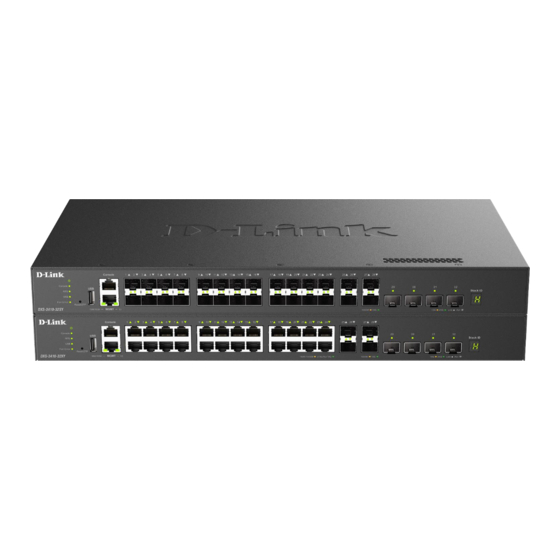
DXS-3410 Series Layer 3 Stackable Managed Switch Hardware Installation Guide Figure 2-2 DXS-3410-32SY Front Panel This following table lists the front panel components unique to the DXS-3410-32SY: Port Type Port Number Description SFP+ Ports Ports 1 to 28 This switch is equipped with 28 SFP+ Ethernet ports that can operate at 1 and 10 Gbps. - Page 9 DXS-3410 Series Layer 3 Stackable Managed Switch Hardware Installation Guide Color Status Description Fan is operating normally MGMT (Link/Act) Green On (Solid) Active 1 Gbps connection through the port (Out-Of-Band port) On (Blinking) Data transmitted and received through the port...
-
Page 10: Rear Panel Components
DXS-3410 Series Layer 3 Stackable Managed Switch Hardware Installation Guide Rear Panel Components The rear panel features components like an AC power socket, a security lock, an electrical ground point, and more. Figure 2-5 DXS-3410-32XY Rear Panel Figure 2-6 DXS-3410-32SY Rear Panel... -
Page 11: Side Panel Components
DXS-3410 Series Layer 3 Stackable Managed Switch Hardware Installation Guide Side Panel Components The side panels feature components like rack-mounting screw holes, heat dissipating fans and vents. Figure 2-7 DXS-3410-32XY/32SY Side Panels The fans are capable of automatically adjusting their speed based on the IC sensor's temperature readings. This feature is highly sensitive, enabling precise control of the internal temperature by accurately regulating the fan speed. -
Page 12: Installation
DXS-3410 Series Layer 3 Stackable Managed Switch Hardware Installation Guide 3. Installation Installation Guidelines This section will cover the hardware installation guidelines that the user needs to adhere to for the correct and safe installation of this Switch in the suitable environment. -
Page 13: Installing The Switch In A Standard 19" Rack
DXS-3410 Series Layer 3 Stackable Managed Switch Hardware Installation Guide Installing the Switch in a Standard 19" Rack This section is used to guide the user through installing the Switch into a Switch rack. The Switch can be mounted in a standard 19"(1U) rack using the rack mounting kit included in the package contents. -
Page 14: Installing Transceivers Into The Transceiver Ports
DXS-3410 Series Layer 3 Stackable Managed Switch Hardware Installation Guide Installing Transceivers into the Transceiver Ports The Switch is outfitted with SFP+ and SFP28 ports designed for linking different networking devices to this Switch, especially those incompatible with the standard RJ45 wiring connection. Typically, these ports establish connections between this Switch and optical fiber links, facilitating communication over considerable distances. -
Page 15: Connecting Ac Power To The Switch
DXS-3410 Series Layer 3 Stackable Managed Switch Hardware Installation Guide Connecting AC Power to the Switch To connect AC power to the Switch, insert one end of the AC power cord into the Switch's AC power socket, and the other end into the local AC power source outlet. The Switch lacks a power switch/button; it will initiate powering on automatically. - Page 16 DXS-3410 Series Layer 3 Stackable Managed Switch Hardware Installation Guide Slide the retainer through the tie wrap until the end of the Circle the tie of the retainer around the power cord and cord. into the locker of the retainer.
-
Page 17: Installing The Redundant Power Supply (Rps)
The D-Link DPS-500A is the recommended RPS for the Switch. This RPS is specifically engineered to adhere to the wattage requirements of D-Link's Ethernet Switches, and it can be linked to the RPS port of the Switch using a 14-pin DC power cable. - Page 18 DXS-3410 Series Layer 3 Stackable Managed Switch Hardware Installation Guide A green LED on the front panel of the RPS unit will illuminate, indicating a successful connection. Reattach the AC power cord to the AC power port of the Switch. The RPS LED indicator on the front panel of the Switch will confirm the presence and operation of the RPS.
-
Page 19: Switch Connections
DXS-3410 Series Layer 3 Stackable Managed Switch Hardware Installation Guide 4. Switch Connections Stacking the Switch Switches in the series can be physically stacked by utilizing the last four ports on the front panel of the Switch. It is possible to stack up to nine Switches, which can then be managed through a single connection to any of the LAN ports using Telnet, the Web UI, and SNMP. - Page 20 DXS-3410 Series Layer 3 Stackable Managed Switch Hardware Installation Guide In the following diagram, Switches are stacked in the Duplex Chain topology. Figure 4-1 Duplex Chain Stacking Topology...
- Page 21 DXS-3410 Series Layer 3 Stackable Managed Switch Hardware Installation Guide In the following diagram, Switches are stacked in the Duplex Ring topology. Figure 4-2 Duplex Ring Stacking Topology...
-
Page 22: Switch To Switch
DXS-3410 Series Layer 3 Stackable Managed Switch Hardware Installation Guide Switch to Switch The Switch can be used to connect to any other Switch in the network. This network topology is used when this Switch or the other switch does not have enough ports to cater for all the end nodes in the network. - Page 23 DXS-3410 Series Layer 3 Stackable Managed Switch Hardware Installation Guide The diagram below displays a Server connected to the Switch. Figure 4-5 Switch to End Node (Server)
-
Page 24: Switch Management
Console port provides an Out-Of-Band (OOB) connection to the CLI, while the LAN ports offer an in-band connection to the CLI using Telnet or SSH. NOTE: For more information about the CLI, refer to the DXS-3410 Series CLI Reference Guide. Connecting to the Console Port The Console port is used to establish a connection with the Switch's CLI. -
Page 25: Logging Into The Cli
DXS-3410 Series Layer 3 Stackable Managed Switch Hardware Installation Guide Logging into the CLI When we connect to the CLI for the first time, we'll be required to change the login password. Enter the default username and password to get the process started. The default username and password is admin. -
Page 26: Web User Interface (Web Ui)
DXS-3410 Series Layer 3 Stackable Managed Switch Hardware Installation Guide Web User Interface (Web UI) The Web UI, which offers a more graphical interface, grants access to the majority of the software features present on the Switch. These features can be enabled, configured, disabled, or monitored through any standard web browser, such as Microsoft's Internet Explorer, Mozilla Firefox, Google Chrome, or Safari. - Page 27 DXS-3410 Series Layer 3 Stackable Managed Switch Hardware Installation Guide The following is a screen capture of the Web User Interface (Web UI): Figure 5-3 Web User Interface (Standard Mode) NOTE: For more information about the Web UI, refer to the DXS-3410 Series Web UI Reference Guide.
-
Page 28: Snmp-Based Management
DXS-3410 Series Layer 3 Stackable Managed Switch Hardware Installation Guide SNMP-based Management The Switch can be managed through an SNMP-compatible console program. It supports versions 1, 2c, and 3 of the Simple Network Management Protocol (SNMP). An SNMP agent decodes incoming SNMP messages and replies to requests with MIB (Management Information Base) objects stored in the database. -
Page 29: Appendix A - Technical Specifications
DXS-3410 Series Layer 3 Stackable Managed Switch Hardware Installation Guide Appendix A - Technical Specifications Physical Specifications Feature Description Dimensions DXS-3410-32XY 441 mm (W) x 250 mm (D) x 44 mm (H) DXS-3410-32SY 441 mm (W) x 250 mm (D) x 44 mm (H) - Page 30 DXS-3410 Series Layer 3 Stackable Managed Switch Hardware Installation Guide Performance Specification Feature Description Switching Capacity DXS-3410-32XY 760 Gbps DXS-3410-32SY 760 Gbps MAC Address Table Up to 288K entries (1K static MAC addresses) Physical Stacking Topology Duplex Ring and Duplex Chain...
- Page 31 DXS-3410 Series Layer 3 Stackable Managed Switch Hardware Installation Guide Feature Description IEEE 802.3x (Full-Duplex, Flow Control) The RJ45 ports support the following features: Back pressure for half-duplex mode Head-of-line blocking prevention Manual/auto MDI/MDIX configuration Auto-negotiation for each port...
- Page 32 4 x 25G SFP28 to 1 x 100G QSFP28 30 AWG NOTE: Only HW version A2 DEM-410T transceivers are compatible with DXS-3410 Series switches. Install these transceivers exclusively in ports 25 through 32 within environments with an ambient temperature not exceeding 40 °C (104 °F). When using the DEM-410T, do not force the port speed.
-
Page 33: Appendix B - Cables And Connectors
DXS-3410 Series Layer 3 Stackable Managed Switch Hardware Installation Guide Appendix B - Cables and Connectors Ethernet Cable When connecting the Switch to another switch, a bridge, or hub, a straight-through Category 5/5e/6a/7 cable is necessary. The following diagrams and tables show the standard RJ45 receptacle/connector and their pin assignments. -
Page 34: Console Cable
DXS-3410 Series Layer 3 Stackable Managed Switch Hardware Installation Guide Console Cable A console cable is used to connect to the RJ45 console port of the Switch to access the command line interface. The following diagram and table show the standard RJ45 to RS-232cable and pin assignments. -
Page 35: Appendix C - Erps Information
DXS-3410 Series Layer 3 Stackable Managed Switch Hardware Installation Guide Appendix C - ERPS Information Only hardware-based ERPS supports the Fast Link Drop Interrupt feature with a recovery time of 50 milliseconds in a 16-node ring. The distance must be less than 1200 kilometers. -
Page 36: Safety/Sécurité
DXS-3410 Series Layer 3 Stackable Managed Switch Hardware Installation Guide Safety/Sécurité Safety Instructions Please pay careful attention to the following safety guidelines to ensure your own personal safety and to help protect your system from potential damage. Safety Cautions To greatly reduce the risk of physical injury, electrical shock, fire, and damage to equipment, observe the following precautions. -
Page 37: Consignes De Sécurité
DXS-3410 Series Layer 3 Stackable Managed Switch Hardware Installation Guide Position system cables and power cables carefully. Route cables so that they cannot be stepped on or tripped over. Be sure that nothing rests on any cables. Do not modify power cables or plugs. Consult a licensed electrician or your power company for site modifications. - Page 38 DXS-3410 Series Layer 3 Stackable Managed Switch Hardware Installation Guide Précautions générales de sécurité: Danger électrique: Seul le personnel qualifié doit effectuer les procédures d'installation. Avant de procéder à l'entretien, débranchez tous les cordons d'alimentation pour mettre le périphérique hors tension.
-
Page 39: General Precautions For Rack-Mountable Products
DXS-3410 Series Layer 3 Stackable Managed Switch Hardware Installation Guide General Precautions for Rack-Mountable Products Please pay careful attention to the following precautions concerning rack stability and safety. Systems are considered to be components in a rack. Thus, a component refers to any system, as well as to various peripherals or supporting... -
Page 40: Protecting Against Electrostatic Discharge
DXS-3410 Series Layer 3 Stackable Managed Switch Hardware Installation Guide Protecting Against Electrostatic Discharge Static electricity can harm delicate components inside the system. To prevent static damage, discharge static electricity from your body before touching any of the electronic components, such as the microprocessor. This can be done by periodically touching an unpainted metal surface on the chassis. -
Page 41: Warranty & Technical Support
The customer must submit with the product as part of the claim a written description of the Hardware defect or Software nonconformance in sufficient detail to allow D-Link to confirm the same, along with proof of purchase of the product (such as a copy of the dated purchase invoice for the product) if the product is not registered. - Page 42 D-Link Corporation/D-Link Systems, Inc., as stipulated by the United States Copyright Act of 1976 and any amendments thereto. Contents are subject to change without prior notice. Copyright 2004 by D-Link Corporation/D-Link Systems, Inc.
- Page 43 Product Registration Register your D-Link product online at http://support.dlink.com/register/ Product registration is entirely voluntary and failure to complete or return this form will not diminish your warranty rights.
- Page 44 This guide is only for initial configuration. Please refer to the user manual to learn more or visit http://www.mydlink.com for more information. Also feel free to contact us. U.S. and Canadian customers can contact D-Link Technical Support through our website. http://support.dlink.com Canada...
- Page 45 Europe customers TECHNICAL SUPPORT TECHNISCHE UNTERSTÜTZUNG ASSISTANCE TECHNIQUE ASISTENCIA TÉCNICA SUPPORTO TECNICO TECHNISCHE ONDERSTEUNING POMOC TECHNICZNA TECHNICKÁ PODPORA TECHNIKAI TÁMOGATÁS eu.dlink.com/support TEKNISK STØTTE TEKNISK SUPPORT TEKNINEN TUKI TEKNISK SUPPORT ASSISTÊNCIA TÉCNICA ΤΕΧΝΙΚΉ ΥΠΟΣΤΉΡΙΞΗ TEHNIČKA PODRŠKA TEHNIČNA PODPORA SUPORT TEHNIC ТЕХНИЧЕСКА ПОДДРЪЖКА TECHNICKÁ...
- Page 46 Indonesia - www.dlink.co.id Malaysia - www.dlink.com.my Philippines - www.dlink.com.ph Vietnam - www.dlink.com.vn Korea customers Tel : 1899-3540 Monday to Friday 9:30am to 6:30pm Web : http://d-link.co.kr E-mail : support@kr.dlink.com New Zealand customers Tel: 0800-900-900 24/7 Technical Support Web: http://www.dlink.co.nz E-mail: support@dlink.co.nz...
- Page 47 D-Link Middle East - Dubai, U.A.E. Plot No. S31102, Jebel Ali Free Zone South, P.O.Box 18224, Dubai, U.A.E. Tel: +971-4-8809022 Fax: +971-4-8809066 / 8809069 Technical Support: +971-4-8809033 General Inquiries: info.me@me.dlink.com Tech Support: support.me@me.dlink.com Egypt 19 Helmy El-Masry, Almaza, Heliopolis Cairo, Egypt Tel: +202-24147906 Technical Support Center no.
- Page 48 Обновления программного обеспечения и документация доступны на Интернет-сайте D-Link. D-Link предоставляет бесплатную поддержку для клиентов в течение гарантийного срока. Клиенты могут обратиться в группу технической поддержки D-Link по телефону или через Интернет. Техническая поддержка компании D-Link работает в круглосуточном режиме ежедневно, кроме официальных праздничных дней. Звонок...
- Page 49 Офисы Россия Москва, Графский переулок, 14 Հայաստան Тел. : +7 (495) 744-00-99 Երևան, Դավթաշեն 3-րդ E-mail: mail@dlink.ru թաղամաս, 23/5 Հեռ.՝ +374 (10) 39-86-67 Україна Էլ. փոստ՝ info@dlink.am Київ, вул. Межигірська, 87-А Тел.: +38 (044) 545-64-40 Lietuva E-mail: ua@dlink.ua Vilnius, Žirmūnų 139-303 Tel.: +370 (5) 236-36-29 Moldova E-mail: info@dlink.lt...
- Page 50 Soporte Técnico Para Usuarios En Latino America Por favor revise el número telefónico del Call Center de su país en http://www.dlinkla.com/soporte/call-center Soporte Técnico de D-Link a través de Internet Horario de atención Soporte Técnico en www.dlinkla.com e-mail: soporte@dlinkla.com & consultas@dlinkla.com Clientes de Brasil Caso tenha dúvidas na instalação do produto, entre em contato com o...
- Page 51 D-Link 友訊科技 台灣分公司 技術支援資訊 如果您還有任何本使用手冊無法協助您解決的產品相關問題,台灣、香港或是澳門用戶 可至網站、電子郵件或電話等方式與D-Link技術支援工程師聯絡。 台灣 D-Link 免付費技術諮詢專線 台灣技術諮詢服務專線 0800-002-615 台灣手機付費電話 (02) 6600-0123#8715 台灣網站: http://www.dlink.com.tw 台灣電子郵件: dssqa_service@dlink.com.tw 產品保固期限、台灣技術諮詢時間、維修據點查詢,請參考 http://www.dlink.com.tw 網頁 說明 香港、澳門 D-Link 技術諮詢專線 http://www.dlink.com.hk 香港網站: 香港、澳門維修據點查詢請參考 http://www.dlink.com.hk/contact.html 網頁說明。 如果您是其他地區的用戶,請參考 D-Link 網站 www.dlink.com 查詢全球各地分公司的聯絡 資訊以取得相關支援服務。...
- Page 52 Pelanggan Indonesia Update perangkat lunak dan dokumentasi pengguna dapat diperoleh pada situs web D-Link. Dukungan Teknis untuk pelanggan: Tel: 0800-14014-97 (Layanan Bebas Pulsa) Dukungan Teknis D-Link melalui Internet: Pertanyaan Umum: sales@id.dlink.com Bantuan Teknis: support@id.dlink.com Website : http://www.dlink.co.id 日本のお客様 この度は弊社製品をお買い上げいただき、誠にありがとうございます。 製品に同梱されている保証書の購入元にお問い合わせください。...
- Page 53 8. What category best describes your company? Aerospace Engineering Education Finance Hospital Legal Insurance/Real Estate Manufacturing Retail/Chain store/Wholesale Government Transportation/Utilities/Communication System house/company Other________________________________ 9. Would you recommend your D-Link product to a friend? Don't know yet 10.Your comments on this product? __________________________________________________________________________________________ __________________________________________________________________________________________...
Need help?
Do you have a question about the DXS-3410 Series and is the answer not in the manual?
Questions and answers