Table of Contents
Advertisement
Document Type: Service Manual
Version: V1.0 10172018
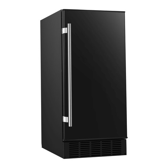
SERVICE MANUAL
Undercounter Crescent Ice Maker
MODELS:
IB250BL, IB250SS, IB250SSOD, and IB250WH
CAUTION: READ ALL SAFETY PRECAUTIONS IN THIS
MANUAL BEFORE SERVICING THE UNIT
EdgeStar, 8606 Wall St, Suite 1800, Austin, TX 78754
support.edgestar.com • service@edgestar.com • edgestar.com
*Warranty service should be performed by an authorized service representative only.
Advertisement
Table of Contents
Troubleshooting

Related Manuals for EdgeStar IB250SS


Summary of Contents for EdgeStar IB250SS
- Page 1 IB250BL, IB250SS, IB250SSOD, and IB250WH CAUTION: READ ALL SAFETY PRECAUTIONS IN THIS MANUAL BEFORE SERVICING THE UNIT EdgeStar, 8606 Wall St, Suite 1800, Austin, TX 78754 support.edgestar.com • service@edgestar.com • edgestar.com *Warranty service should be performed by an authorized service representative only.
-
Page 2: Table Of Contents
Contents Safety Precautions ........................... 1 Electrical Safety .......................... 2 General Safety ..........................3 Specifications ..........................4 Parts Breakdown ..........................5 Exploded View..........................5 Parts List ............................. 5 Wiring Diagram ..........................6 Refrigeration System Diagram ....................... 7 Service Diagnosis Overview ......................8 Troubleshooting Guide ....................... -
Page 3: Electrical Safety
Electrical Safety Do not exceed the power outlet ratings. It is recommended that the unit be connected to its own circuit. A standard electrical supply (120V, 60Hz), that is properly grounded in accordance with the National Electrical Code and all state and local codes and ordinances is required. ... -
Page 4: General Safety
General Safety Always unplug an appliance from the power supply before attempting any service. Disconnect the power cord by grasping the plug, not the cord. Do not allow children or pets to play on or in the appliance. ... -
Page 5: Specifications
Specifications Model IB250SS General Features Ice Production Capacity 25lbs/24 hrs Ice Storage capacity 11lbs removable ice bucket Ice Shape Crescent Shaped Cube Ice Size (Inches(mm)) 1/2"x3/4"x2-1/2" (12x20x60) Ice Weight (g) Ice quantity per cycle Ice making /harvesting 1.8/1.5 rated current (amp) Water Consumption Use less than 3 gallons of water for approximately 23 lbs. -
Page 6: Parts Breakdown
Parts Breakdown Exploded View Parts List Part Name Part Name Door Fan motor Handle Fan motor bracket Ice storage bin Power cord Ice making module Water inlet panel Cabinet Water inlet connecter Back panel Water inlet pipe Hinge pin Water inlet pipe connecter Top hinge Water supply hose Ice scoop... -
Page 7: Wiring Diagram
Wiring Diagram... -
Page 8: Refrigeration System Diagram
Refrigeration System Diagram During the ice making stage the hot refrigerant gas is pumped out of the compressor to the condenser. The hot gas is cooled by fan forced air after passing through the condenser. The evaporator / ice module is cooled by the refrigerant. Ice is formed in the module after water from the water inlet valve fills the ice mold. -
Page 9: Service Diagnosis Overview
Service Diagnosis Overview WARNING: Only a qualified technician should service this product. Equipment damage, injury or death could result from the improper servicing of this unit. EdgeStar accepts no responsibility or liability for damage to equipment, injury or death that may result from improper service or operation of this product. -
Page 10: Troubleshooting Flowchart
Troubleshooting Flowchart... -
Page 11: Servicing The Ice Maker
Servicing the Ice Maker Adjusting the Water Fill Level Remove the white cover from the front of the ice module to access the fill control screw. The amount of water that fills the ice mold is controlled by the length of time the water valve is open. -
Page 12: Adjusting The Thermostat And Ice Harvest Time
Adjusting the Thermostat and Ice Harvest Time The ice harvest control adjusts the temperature at which the ice is harvested from the ice mold. A colder setting results in harder ice, which is slower to melt, but also increases ice production time. - Page 13 To remove the cover first insert a flat tip screwdriver into the tab. Next, push down to unlock and remove the cover. Pull off the start relay first, then the overload protector. Remove the wires and connect them to the new start relay and overload protector.
-
Page 14: Replacing The Ice Making Module
Replacing the Ice Making Module Warning: Unplug the unit before servicing to avoid electrical shock. Remove the back panel and then remove the styrofoam block covering the ice making module’s power cable. Disconnect the Water line power cable for the ice module at its Power cable connector. - Page 15 Remove the three (3) screws from the bottom of the module and take off the bottom plate. Loosen the two (2) screws attaching the ice module to the side of the cabinet wall about 1/4 “. The ice module hangs on the screws so they do not need to be completely...
- Page 16 Replace the old thermal pad by adhering the new one to the bottom of the new ice module. Install the new ice module by feeding the power cord through the channel in the back of the cabinet. Make sure the thermostat wire is inserted into hole in the back of the ice...
-
Page 17: Replacing The Water Valve
Reinstall the bottom plate to the module with the three screws removed previously. Reconnect the power cable. Re- caulk the power cable hole in the back of the unit. Replacing the Water Valve Remove the two screws securing the kick plate to the front of the unit and then remove the kick plate. - Page 18 Disconnect the wires to the water valve. Remove the back panel from the unit. Carefully maneuver the water valve through the back of the unit so you can access the valve and the two water lines connected to it. Remove the blue lock ring with fingernail or small flathead screwdriver.
-
Page 19: Replacing The Condenser Fan
Insert the water lines into the new valve in the correct ports by simply pushing them in until they stop. The compression fittings will hold the lines securely. Replace the blue lock ring on the module port. Carefully reposition the new water valve in through the back of the unit and resecure it to its... -
Page 20: Replacing The Thermostat
Stand unit upright and access the fan through the back. Carefully remove old fan, remove it’s wire connections and replace with new fan. Make sure wire connections are secured to new fan motor. Replace the two screws on the bottom of the unit that secure the fan in place. - Page 21 Remove the front kick plate to access the thermostat. Remove the two screws that secure the thermostat dial to the base of the unit. Remove the wire connections from the old thermostat and secure them onto the new thermostat in their correct positions.
- Page 22 DATE REVISION NOTES 10/17/2018 INITIAL DOCUMENT EdgeStar, 8606 Wall St, Suite 1800, Austin, TX 78754 support.edgestar.com • service@edgestar.com • edgestar.com *Warranty service should be performed by an authorized service representative only.
Need help?
Do you have a question about the IB250SS and is the answer not in the manual?
Questions and answers
What is the part number for compressor relay