Table of Contents
Advertisement
Document Type: Service Manual
Version: V1.0 02062018
SERVICE MANUAL
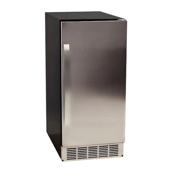
EdgeStar 45 Lb. Undercounter Clear Ice Maker
with Drain Pump
MODEL:
IB450SSP
CAUTION: READ ALL SAFETY PRECAUTIONS IN
THIS MANUAL BEFORE SERVICING THE UNIT
EdgeStar, 8606 Wall St, Suite 1800, Austin, TX 78754
support.edgestar.com • service@edgestar.com • edgestar.com
*Warranty service should be performed by an authorized service representative only.
Advertisement
Table of Contents
Troubleshooting

Related Manuals for EdgeStar IB450SSP


Summary of Contents for EdgeStar IB450SSP
- Page 1 Drain Pump MODEL: IB450SSP CAUTION: READ ALL SAFETY PRECAUTIONS IN THIS MANUAL BEFORE SERVICING THE UNIT EdgeStar, 8606 Wall St, Suite 1800, Austin, TX 78754 support.edgestar.com • service@edgestar.com • edgestar.com *Warranty service should be performed by an authorized service representative only.
-
Page 2: Table Of Contents
COOLING SYSTEM OVERVIEW ......................4 COOLING SYSTEM PARTS LIST ......................5 WATER SYSTEM ............................. 6 ELECTRICAL SYSTEM ..........................7 IB450SSP CONTROLS / CONTROL BOX ....................8 LEDS AND BUTTONS ..........................8 ICE CUBE SIZE ADJUSTMENT GUIDE: ....................8 EXPLODED VIEW DIAGRAM........................10 PARTS LIST .............................. -
Page 3: Electrical Safety
Electrical Safety Do not exceed the power outlet ratings. It is recommended that the unit be connected to its own circuit. A standard electrical supply (120V, 60Hz), that is properly grounded in accordance with the National Electrical Code and all state and local codes and ordinances is required. ... -
Page 4: General Safety
General Safety Always unplug an appliance from the power supply before attempting any service. Disconnect the power cord by grasping the plug, not the cord. Do not allow children or pets to play on or in the appliance. ... -
Page 5: Ib450Ssp Introduction
IB450SSP Introduction The IB450SSP is comprised of 3 systems: The Cooling System, Water System and Electrical System. Note: Please refer to the IB450SSP User Manual for installation and other use and care guidelines. Cooling System Overview... -
Page 6: Cooling System Parts List
Cooling System Parts List ITEM NO. DESCRIPTION Condenser Multi-connection copper pipe Hot gas solenoid valve Filter Dryer Capillary tube Hot gas tube Suction tube Compressor Fan motor Fan motor bracket Fan blade Discharge tube Wiring harness Control box 39.1 Temperature sensor for the condenser 39.2 Temperature sensor of the evaporator Evaporator (Ice Mold) -
Page 7: Water System
Water System When the water supply hose (No. 38) is connected with the main water supply, water will fill the water bin (No. 57) through the float valve (No. 32) until water fills the bin enough to make the float valve close. During ice-making stage, water is pumped from the water bin to the water distribution tube (No. -
Page 8: Electrical System
Electrical System Ice-Making Stage - The compressor, condenser fan and pump are powered on, the water inlet valve and hot gas solenoid valve close and the Green LED on the control panel is lit. When the unit is in this stage it is controlled by a temperature probe on the evaporator. -
Page 9: Ib450Ssp Controls / Control Box
IB450SSP Controls / Control Box LEDs and Buttons Red LED: Ice-Full indicator light. This LED is lit when the ice storage bin is full of ice or there is something between the two arms of the ice-full sensor in the ice storage bin. The electrical components turn off and the unit will go to sleep. - Page 10 Smaller ice cube setting: Pressing the Clean button decreases the size of the ice cubes. The Ice-Full/Red LED will flash as you decrease the ice size and will finally blink once it has reached the smallest setting. Larger ice cube setting: By pressing the Mode button, you can increase the size of the ice cubes.
-
Page 11: Exploded View Diagram
Exploded View Diagram... -
Page 12: Parts List
Parts List Description Description Door handle Drain connector Door Bottom hinge Ice storage bin Left bracket Ice scoop Power cord Water distribution tube Wire harness Evaporator (ice mold) Capillary tube Evaporator sensor Filter dryer Ice slide way Compressor Ice full switch Discharge pipe Water bin Right bracket... -
Page 13: Troubleshooting
TROUBLESHOOTING Basic Precautions 1. Make sure the unit is connected to a 115 Volt, 60Hz. AC only 15 amp electrical supply and is properly grounded to protect against electrical shock. 2. Make sure the power cord is not damaged. Basic Checks Listen ... -
Page 14: Advanced Troubleshooting Guide
Advanced Troubleshooting Guide The troubleshooting guide in the user manual should be referred to before this guide. Turn to this guide when the user manual does not solve the issue. The Unit Does Not Make Ice Problem Check point Possible Cause Correction Unit will not turn Plug... - Page 15 Water Pump The housing of water pump Replace water pump. leaks. Compressor will Wiring connections A wiring connection is Check, repair and/or re- not run incorrect, damaged or loose. connect. Start Relay and One or both defective. Replace both relay and Overload Protector overload protector.
- Page 16 Low Ice Production Check point Possible Cause Correction Problem Cooling Refrigerant Partial refrigerant leak. Repair leak and System recharge. Condenser The condenser may be dirty. Clean the condenser. Ambient Temperature The ambient temperature is Adjust the ambient above 90F or below 65F. temperature or move unit to better location.
- Page 17 Ice Cubes Are Deformed or Wrong Size Problem Check point Possible Cause Correction Ice Cubes Too Condenser The condenser or fans are Clean the condenser and Small dirty or the air vents are fans. Leave space around covered. the machine. Ambient Temperature The ambient temperature is Adjust the ambient...
- Page 18 Other problems Check point Possible Cause Correction Problem The Unit Body Ground The ground plug is broken. Replace power cord. is Electrified Lines Shorted wiring. Adjust, reconnect /replace wires. Electric component Shorted electric component. Replace component. Scales Occur Frequently Water Quality The water quality is poor.
-
Page 19: Replacing Water System Components
Replacing Water System Components Replacing the water pump Disconnect electrical power. Remove the rear cover Unplug the lines connected to the water pump, the water outlet tube and the water inlet tube. Loosen the screws and replace with a new one. ... -
Page 20: Replacing Cooling System Components
Replacing Cooling System Components NOTE: Please see the cooling system diagram. Please check for refrigerant leaks after any service is performed to the cooling system. Replacing the compressor start relay and overload protector. To replace the relay and overload protector, remove the rear panel, locate the compressor, take the clip off the cover to relay and overload protector, open the cover, replace the relay and overload protected. - Page 21 DATE REVISION NOTES 02/06/2018 INITIAL DOCUMENT EdgeStar, 8606 Wall St, Suite 1800, Austin, TX 78754 support.edgestar.com • service@edgestar.com • edgestar.com *Warranty service should be performed by an authorized service representative only.
Need help?
Do you have a question about the IB450SSP and is the answer not in the manual?
Questions and answers