Table of Contents
Advertisement
Quick Links
C099-F9P
Application Board (Rev. B)
User Guide
Abstract
The C099-F9P board enables customers to evaluate RTK operation with the ZED-F9P high precision
GNSS receiver. The board provides short-range wireless connection via Bluetooth® or Wi-Fi for
receiving correction data and logging via wireless connectivity.
www.u-blox.com
UBX-18063024 - R03
Advertisement
Table of Contents

Subscribe to Our Youtube Channel
Related Manuals for u-blox C099-F9P


Summary of Contents for u-blox C099-F9P
- Page 1 Application Board (Rev. B) User Guide Abstract The C099-F9P board enables customers to evaluate RTK operation with the ZED-F9P high precision GNSS receiver. The board provides short-range wireless connection via Bluetooth® or Wi-Fi for receiving correction data and logging via wireless connectivity.
-
Page 2: Document Information
The information contained herein is provided “as is” and u-blox assumes no liability for its use. No warranty, either express or implied, is given, including but not limited to, with respect to the accuracy, correctness, reliability and fitness for a particular purpose of the information. -
Page 3: Table Of Contents
Contents ................................3 Introduction ............................. 5 1.1 Package contents ............................6 1.2 Additional sources of information ......................6 C099-F9P quick start ........................... 7 2.1 Starting up ..............................7 C099-F9P description .......................... 9 3.1 Component overview ..........................9 3.2 Component identification ......................... 9 ZED-F9P status LEDs ........................ - Page 4 C099-F9P - User Guide B.2.1 Patch antenna element specification ..................28 B.2.2 LNA electrical specification ......................29 B.2.3 Overall performance ......................... 29 Mechanical board dimensions ......................30 C099-F9P schematics ........................31 ODIN-W2 firmware upload via JTAG .................... 38 Related documents ........................... 39 Revision history ............................
-
Page 5: Introduction
C099-F9P - User Guide Introduction The C099-F9P board is a convenient tool that allows customers to become familiar with the u-blox ZED-F9P high precision GNSS module. The board provides facilities for evaluating the product and demonstrating its key features. The C099-F9P application board offers: •... -
Page 6: Package Contents
ZED-F9P Integration Manual, Doc. No. UBX-18010802 • ZED-F9P Interface Description, Doc. No. UBX-18010854 • Download u-center: https://www.u-blox.com/en/product/u-center-windows and the u-center User Guide: https://www.u-blox.com/sites/default/files/u-center_UserGuide_(UBX-13005250).pdf • Download the u-blox GNSS Sensor and VCP Device Driver guide: https://www.u-blox.com/sites/default/files/products/documents/u-blox-GNSS-Sensor-and-VCP- Device-Driver_UserGuide_(UBX-15022397).pdf UBX-18063024 - R03 Introduction Page 6 of 40... -
Page 7: C099-F9P Quick Start
Device Manager. Set the baud rate to 460’800 baud. See section 4.3.1 for detailed instructions. • The TP LED on the C099-F9P board will blink in blue color. Figure 3 below shows a typical u-center view with active satellite signal levels. - Page 8 C099-F9P - User Guide Figure 3: u-center showing a view of the ZED-F9P default operation UBX-18063024 - R03 C099-F9P quick start Page 8 of 40...
-
Page 9: C099-F9P Description
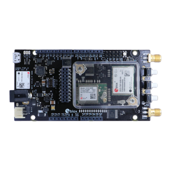
C099-F9P - User Guide C099-F9P description 3.1 Component overview The C099-F9P houses the ZED-F9P RTK high precision positioning module plus an ODIN-W2 module for wireless short-range communications. An FTDI component provides dedicated COM port connections with the ZED-F9P and ODIN-W2 via USB. - Page 10 C099-F9P - User Guide GNSS antenna connector Wi-Fi/BT antenna connector ZED-F9P Multi band GNSS RTK module ODIN-W2 Multi-radio module J2, J3, J8, J9 Arduino Uno connectors DC power jack Battery connector USB (ZED-F9P USB and UART, ODIN-W2 UART ports) Figure 5: Main components and USB ports...
-
Page 11: Zed-F9P Status Leds
C099-F9P - User Guide ZED-F9P and ODIN-W2 reset button ZED-F9P Safeboot button ODIN-W2 Switch 0 interrupt button ODIN-W2 activity LED ODIN-W2 Safeboot pins GNSS LEDs: TP, RTK, GeoFence Battery charger LED Figure 6: Switches and LEDs ☞ The MicroSD card slot is not used in this version of the board. The ODIN-W2 Switch 0 interrupt is not required for normal customer use. -
Page 12: Odin-W2 Activity Led
Failed SPP data packet transmission Blinking red Weak signal, SPP connection failure Table 1: LED activity states and colors ODIN-W2 activity LED Figure 8: ODIN-W2 Activity LED position on C099-F9P board UBX-18063024 - R03 C099-F9P description Page 12 of 40... -
Page 13: Using The C099-F9P
C099-F9P - User Guide Using the C099-F9P The ZED-F9P is shipped with the latest firmware and the ODIN-W2 is pre-configured as a Bluetooth serial device. Information on updating either module’s firmware is provided in section 6. 4.1 Powering the board The board can be powered from a variety of sources: •... -
Page 14: Gnss Rf Input
4.2 GNSS RF input The C099-F9P board should be used with the antenna supplied with the kit. If another active antenna is used, be aware that the RF input has a bias output designed to supply 3.3 V DC with a 70 mA maximum current load. -
Page 15: User Interfaces
C099-F9P - User Guide 4.3 User interfaces The C099-F9P has a number of fixed connection options besides the wireless modes. There is also an additional Arduino R3 / Uno interface for external host connection. The USB connector on the board provides connection via an on-board hub providing: •... -
Page 16: Command Line Interface Of Odin-W2
C099-F9P - User Guide Additional UBX protocol messages can be enabled to view additional information in u-center. For example, the following are typical messages the user can poll or enable for periodic update. • NAV-HPPOSLLH • NAV-RELPOSNED • NAV-SIG •... -
Page 17: Arduino Uno Header Connections
Arduino R3/Uno - see Figure 18 below. All the pin functions besides power are 3.3 V compliant. J9, Arduino D J3, Arduino B J8, Arduino C J2, Arduino A Figure 18: C099-F9P Arduino connectors Figure 19: C099-F9P Arduino R3 connections UBX-18063024 - R03 Using the C099-F9P Page 17 of 40... -
Page 18: Rover Operation Using Ntrip
A suitable host is a PC with internet access. A host runs an NTRIP client and streams RTCM corrections to the C099-F9P through a UART or Bluetooth connection. A user shall note, that messages transmitted through a Bluetooth link are forwarded to I2C bus and vice versa. A user is advised to enable desired messages in both UART and I2C interfaces in ZED-F9P. -
Page 19: Bluetooth Pairing
ODIN-W2 will acknowledge successful reception of the command and inform once it is ready to respond to a pairing request. Next, the user shall perform Bluetooth scan to find the C099-F9P. Every C099-F9P has a predefined unique BT name of type BT_C099-F9P_XYZW as shown in Figure 23. -
Page 20: Odin-W2 As Pairing Initiator
To ensure sufficient radio link quality, a user is advised to check the RSSI level of the host device is well above -80 dBm. Weak signal levels can result in connection losses and limited range. Once the host device has been found by the C099-F9P, the following command starts the pairing process: /bt_bond/run <MAC address>... -
Page 21: Client Spp Connection
COM port. Please note that the baud rate of the BT serial port at the host can be ignored. Client SPP connection In order to use the outgoing port (client port) at the host the user shall set the C099-F9P in server mode by issuing the following command:... -
Page 22: Windows Os Issues With Bluetooth Spp
BT SPP COM port on the host device stalled or disconnected. • Insufficient signal quality between the host device and C099-F9P. To recover the system after a failing BT link, reset ODIN-W2 by pressing the reset button. If ZED-F9P is configured through a Bluetooth link, e.g. using UBX-CGF messages, it is recommended to apply all configurations manually at u-center. -
Page 23: Firmware Updates
This section shows how to update the firmware and re-enable the configuration settings required for the C099-F9P. The user has two possible serial communication channels to update ZED-F9P: UART1 and USB2.0 ports. At the time of writing, the current Microsoft USB driver in Windows 10 does not allow ZED-F9P FW update. - Page 24 C099-F9P - User Guide The following firmware image update window will appear as shown below: Figure 29: Selecting u-center Firmware image folder At the top is the Firmware image file selection window. Click on the button to the right of the window.
- Page 25 C099-F9P - User Guide Figure 32: Click GO for firmware update The firmware update progress indication is shown adjacent to the input window. When programming is complete, the module will start up in a default configuration in which the ZED- F9P serial port is set to 38400 baud.
-
Page 26: Odin-W2 Firmware Update
Prior to firmware upload, the ODIN-W2 must be started in safe boot mode. Proceed by placing a safe boot jumper and reboot C099-F9P. Location of the safe boot pin header and the reset button is depicted in Figure 6. To confirm the ODIN-W2 started in safe boot mode the ODIN-W2 activity LED remains off. -
Page 27: Appendix
FCC, IC, RED, MIC, NCC, KCC*, ANATEL, and ICASA Table 3: Wi-Fi/Bluetooth antenna ☞ The variant included in the C099-F9P kit is with SMA connector and has to be mounted on the corresponding antenna connector of the C099-F9P board if you wish to use Wi-Fi or Bluetooth connectivity. -
Page 28: Patch Antenna Element Specification
C099-F9P - User Guide Figure 34: u-blox dual band GNSS antenna B.2.1 Patch antenna element specification Figure 35: Patch elements specification UBX-18063024 - R03 Appendix Page 28 of 40... -
Page 29: Lna Electrical Specification
C099-F9P - User Guide B.2.2 LNA electrical specification Figure 36: LNA specification B.2.3 Overall performance Figure 37: u-blox multi-band GNSS antenna performance UBX-18063024 - R03 Appendix Page 29 of 40... -
Page 30: C Mechanical Board Dimensions
C099-F9P - User Guide C Mechanical board dimensions Figure 38: C099-F9P rev. B dimensions UBX-18063024 - R03 Appendix Page 30 of 40... -
Page 31: D C099-F9P Schematics
C099-F9P - User Guide D C099-F9P schematics The following pages show the complete schematic for the C099-F9P evaluation board. UBX-18063024 - R03 Appendix Page 31 of 40... - Page 32 C099-F9P - User Guide UBX-18063024 - R03 Appendix Page 32 of 40...
- Page 33 C099-F9P - User Guide UBX-18063024 - R03 Appendix Page 33 of 40...
- Page 34 C099-F9P - User Guide UBX-18063024 - R03 Appendix Page 34 of 40...
- Page 35 C099-F9P - User Guide UBX-18063024 - R03 Appendix Page 35 of 40...
- Page 36 C099-F9P - User Guide UBX-18063024 - R03 Appendix Page 36 of 40...
- Page 37 C099-F9P - User Guide UBX-18063024 - R03 Appendix Page 37 of 40...
-
Page 38: Eodin-W2 Firmware Upload Via Jtag
C099-F9P - User Guide E ODIN-W2 firmware upload via JTAG ODIN-W2 firmware upload is possible through the 10-pin JTAG connector by using the STM Link Utility SW and ST LINK V2 debugger device. STM Link Utility software can be found on https://www.st.com/en/development-tools/stsw-link004.html... -
Page 39: Related Documents
User Guide, Doc. No. UBX-13005250 ZED-F9P Integration Manual, Doc No. UBX-18010802 C099-F9P User Guide (with ODIN-W2 Connectivity SW), Doc No. UBX-18055649 ☞ For regular updates to u-blox documentation and to receive product change notifications, register on our homepage (www.u-blox.com). Revision history Revision... -
Page 40: Contact
C099-F9P - User Guide Contact For complete contact information, visit us at www.u-blox.com. u-blox Offices North, Central and South America Headquarters Asia, Australia, Pacific Europe, Middle East, Africa u-blox America, Inc. u-blox Singapore Pte. Ltd. u-blox AG Phone: +1 703 483 3180...
Need help?
Do you have a question about the C099-F9P and is the answer not in the manual?
Questions and answers