Table of Contents
Advertisement
Quick Links
C212-NORA-B126
NORA-B126 Bluetooth LE audio application board
User guide
Abstract
The C212-NORA-B126 Bluetooth LE audio application board is designed for evaluation of Bluetooth
LE audio and Auracast applications using the NORA-B1 series modules. Fully compliant with the
Bluetooth 5.3 standard, the board hosts the NORA-B126 stand-alone Bluetooth Low Energy module.
This user guide provides an overview and full functional description of the audio board, including a
detailed pin list, block diagram, mechanical and electrical specifications, and ordering information.
Aimed towards developers and other technical staff, this document provides the information
necessary for evaluation and design of LE audio applications on the NORA-B1 series modules.
UBXDOC-1023859458-11406 - R03
C1-Public
www.u-blox.com
Advertisement
Table of Contents

Related Manuals for u-blox C212-NORA-B126


Summary of Contents for u-blox C212-NORA-B126
- Page 1 User guide Abstract The C212-NORA-B126 Bluetooth LE audio application board is designed for evaluation of Bluetooth LE audio and Auracast applications using the NORA-B1 series modules. Fully compliant with the Bluetooth 5.3 standard, the board hosts the NORA-B126 stand-alone Bluetooth Low Energy module.
-
Page 2: Document Information
Disclosure to third parties is permitted for clearly public documents only. The information contained herein is provided “as is” and u-blox assumes no liability for its use. No warranty, either express or implied, is given, including but not limited to, with respect to the accuracy, correctness, reliability, and fitness for a particular purpose of the information. -
Page 3: Table Of Contents
C212-NORA-B126 - User guide Contents Document information ..........................2 Contents ................................3 Functional description ......................... 4 1.1 Overview ................................ 4 1.2 Product features ............................4 1.3 Ordering information ..........................5 1.4 Block diagram .............................. 5 Hardware ..............................6 2.1 Interfaces ..............................6 2.1.1 Switches ............................... -
Page 4: Functional Description
For most use cases, we recommend using two or more application boards. The application board (C212-NORA-B126) is based on the existing the nRF5340 Audio Development Kit that already provides a tool for developing your Bluetooth® Low Energy Audio products like a USB dongle for sending or receiving audio data from a computer, a business headset, a broadcast receiver to catch audio streams, true Wireless Stereo (TWS) earbuds for personal audio playback. -
Page 5: Ordering Information
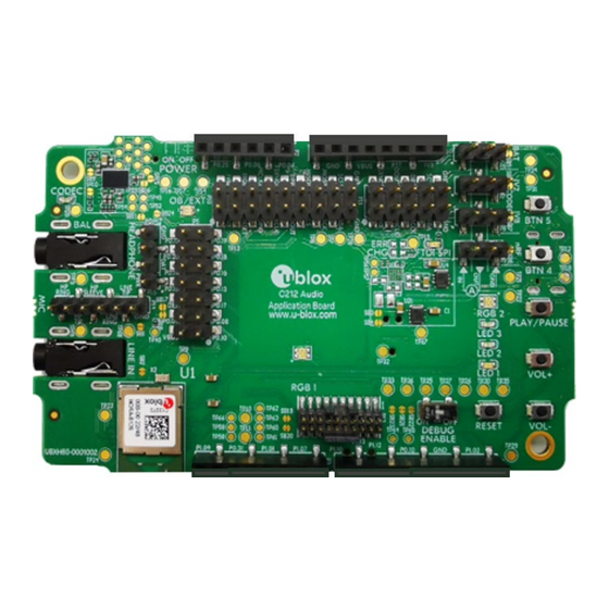
1.4 Block diagram Figure 1 shows a block diagram of the C212-NORA-B126 LE audio board. The board includes I/O ports accessible through pin header connectors. These connectors provide the physical interface for any external device and the USB type C interface used for power supply and communication. The board also features four user-programmable LEDs, five user-programmable buttons, and a microSD card holder for additional storage. -
Page 6: Hardware
Several LED indicators display the status and state of specific tasks. 2.1.1 Switches C212-NORA-B126 has two switches, Power On-Off and DEBUG ENABLE On-Off. The switches are located at the bottom-side and top-side of the board respectively, as shown in Figure 2 Figure 3. -
Page 7: Buttons
Buttons functionality depends on the application. For more details, see the nRF5340 Audio DK User Interface description [11]. 2.1.3 Microphone C212-NORA-B126 has on-board Pulse Density Modulation (PDM) microphone at the bottom side as seen in Figure 5. The PDM microphone (U5) captures audio input. -
Page 8: Leds
C212-NORA-B126 - User guide 2.1.4 LEDs C212-NORA-B126 has LED indicators that are located on the top and bottom side of the board, as shown in Figure 6 Figure Figure 6: LEDs on top side Figure 7: LEDs on bottom side LED functionality depends on the application. - Page 9 C212-NORA-B126 - User guide Figure 8: C212-NORA-B126 board pin headers P1 – P5 Figure 9: C212-NORA-B126 board pin headers P10 UBXDOC-1023859458-11406 - R03 Hardware Page 9 of 37 C1-Public...
-
Page 10: Solder Bridges
Figure 10: C212-NORA-B126 board pin headers P11, P14- P15 2.3 Solder bridges The C212-NORA-B126 LE audio application board has a range of solder bridges for enabling or disabling selected functionalities. Changes to these are not needed for normal use of the board. -
Page 11: Test Points
SB24 Short to bypass analog switch for MCLK Open Table 4: Solder Bridges 2.4 Test points Table 5 describes the test points on the C212-NORA-B126 Bluetooth LE audio application board. Designator Description Size Board side NetTP1-1 IN1LP_1 pin of CS47L63 1.5 mm... - Page 12 C212-NORA-B126 - User guide Designator Description Size Board side TP35 Ground 1.5 mm TP36 NetQ9-1 Debug enable signal 1.5 mm TP37 IMCU_SWDIO Interface MCU Serial Wire Debug data 1.5 mm TP38 IMCU_RESET Interface MCU Reset 1.5 mm TP39 IMCU_SWDCLK Interface MCU Serial Wire Debug clock 1.5 mm...
-
Page 13: Electrical Specifications
VBUS USB input supply voltage Table 7: Input characteristics of voltage supply pins 3.1.4 Current consumption Table 8 shows the current consumption of C212-NORA-B126 LE audio board during a typical use (USB powered). Mode Condition Average Peak Active with FEM enabled 82.5 mA... -
Page 14: Software
Nordic Semiconductor logo. The same LED on the C212-NORA-B126 board is placed in the center of the top side of the C212-NORA-B126. Moreover, C212-NORA-B126 uses the NORA-B126 module, which includes the nRF5340 chip and a front-end module PA/LNA (FEM) for better range and coverage. - Page 15 C212-NORA-B126 - User guide Replace the configuration of nrf21540ek\nrf21540ek_fwd.overlay file with: &gpio_fwd { nrf21540-gpio-if { gpios = <&gpio1 8 0>, <&gpio1 9 0>, <&arduino_header 15 0>, /* pdn-gpios */ <&arduino_header 10 0>, /* ant-sel-gpios */ <&arduino_header 8 0>; /* mode-gpios */ nrf21540-spi-if { gpios = <&arduino_header 16 0>,...
-
Page 16: Mechanical Specification
C212-NORA-B126 - User guide Mechanical specification 5.1 Physical dimensions Figure 11: Physical dimensions of the C212-NORA-B126 LE Audio board UBXDOC-1023859458-11406 - R03 Mechanical specification Page 16 of 37 C1-Public... -
Page 17: Limitations
C212-NORA-B126 - User guide Limitations ☞ Regulatory limitations: C212-NORA-B126 is an application board. It has not been RF certified with worldwide agencies. It may not be offered for sale as an end-user product. 6.1 Hardware The current hardware revision can only accommodate a single microSD card with a storage capacity of up to 16 GB. -
Page 18: Schematics
C212-NORA-B126 - User guide Schematics Figure 12: Top-level schematic (1 of 19) UBXDOC-1023859458-11406 - R03 Schematics Page 18 of 37 C1-Public... - Page 19 C212-NORA-B126 - User guide Figure 13: Interface schematic (2 of 19) UBXDOC-1023859458-11406 - R03 Schematics Page 19 of 37 C1-Public...
- Page 20 C212-NORA-B126 - User guide Figure 14: Connectors schematic (3 of 19) UBXDOC-1023859458-11406 - R03 Schematics Page 20 of 37 C1-Public...
- Page 21 C212-NORA-B126 - User guide Figure 15: User interface schematic (4 of 19) UBXDOC-1023859458-11406 - R03 Schematics Page 21 of 37 C1-Public...
- Page 22 C212-NORA-B126 - User guide Figure 16: Reference circuitry schematic (5 of 19) UBXDOC-1023859458-11406 - R03 Schematics Page 22 of 37 C1-Public...
- Page 23 C212-NORA-B126 - User guide Figure 17: Hardware codex schematic (6 of 19) UBXDOC-1023859458-11406 - R03 Schematics Page 23 of 37 C1-Public...
- Page 24 C212-NORA-B126 - User guide Figure 18: PMIC schematic (7 of 19) UBXDOC-1023859458-11406 - R03 Schematics Page 24 of 37 C1-Public...
- Page 25 C212-NORA-B126 - User guide Figure 19: MCU schematic (8 of 19) UBXDOC-1023859458-11406 - R03 Schematics Page 25 of 37 C1-Public...
- Page 26 C212-NORA-B126 - User guide Figure 20: Supportive circuitry schematic (9 of 19) UBXDOC-1023859458-11406 - R03 Schematics Page 26 of 37 C1-Public...
- Page 27 C212-NORA-B126 - User guide Figure 21: FTDI schematic (10 of 19) UBXDOC-1023859458-11406 - R03 Schematics Page 27 of 37 C1-Public...
- Page 28 C212-NORA-B126 - User guide External Figure 22: Hardware codec select (11 of 19) UBXDOC-1023859458-11406 - R03 Schematics Page 28 of 37 C1-Public...
- Page 29 C212-NORA-B126 - User guide Figure 23: Power switch (12 of 19) UBXDOC-1023859458-11406 - R03 Schematics Page 29 of 37 C1-Public...
- Page 30 C212-NORA-B126 - User guide Figure 24: Hardware codec SPI debug (13 of 19) UBXDOC-1023859458-11406 - R03 Schematics Page 30 of 37 C1-Public...
- Page 31 C212-NORA-B126 - User guide Figure 25: MCU interface schematic (14 of 19) UBXDOC-1023859458-11406 - R03 Schematics Page 31 of 37 C1-Public...
- Page 32 C212-NORA-B126 - User guide Figure 26: Power management schematic (15 of 19) UBXDOC-1023859458-11406 - R03 Schematics Page 32 of 37 C1-Public...
- Page 33 C212-NORA-B126 - User guide Figure 27: Current monitor (16 of 19) UBXDOC-1023859458-11406 - R03 Schematics Page 33 of 37 C1-Public...
- Page 34 C212-NORA-B126 - User guide Figure 28: Switch (17 of 19) UBXDOC-1023859458-11406 - R03 Schematics Page 34 of 37 C1-Public...
- Page 35 C212-NORA-B126 - User guide Figure 29: USB Hub (18 of 19) UBXDOC-1023859458-11406 - R03 Schematics Page 35 of 37 C1-Public...
-
Page 36: Appendix
C212-NORA-B126 - User guide Appendix A Glossary Abbreviation Definition Inter-IC-Sound Integrated Circuit Pulse Density Modulation microSD card micro Secure Digital card Serial Peripheral Interface UART Universal Asynchronous Receiver-Transmitter Universal Serial Bus Input /Output Voltage Table 10: Explanation of the abbreviations and terms used... -
Page 37: Related Documentation
Programming the application [10] Nordic Semiconductor nRF Connect SDK v2.6.0, Release Notes [11] Nordic Semiconductor nRF Connect SDK, User interface ☞ For product change notifications and regular updates of u-blox documentation, register on our website, www.u-blox.com. Revision history Revision Date Name... - Page 38 Mouser Electronics Authorized Distributor Click to View Pricing, Inventory, Delivery & Lifecycle Information: u-blox C212-NORA-B126...
Need help?
Do you have a question about the C212-NORA-B126 and is the answer not in the manual?
Questions and answers