Table of Contents
Advertisement
SAM-M8Q
Easy-to-use u-blox M8 GNSS antenna module
Hardware Integration Manual
Abstract
This document describes the hardware features and
specifications of the SAM-M8Q patch antenna module,
which features the u-blox M8 concurrent GNSS engine with
reception of GPS, GLONASS, Galileo and QZSS signals.
www.u-blox.com
UBX-16018358 - R05
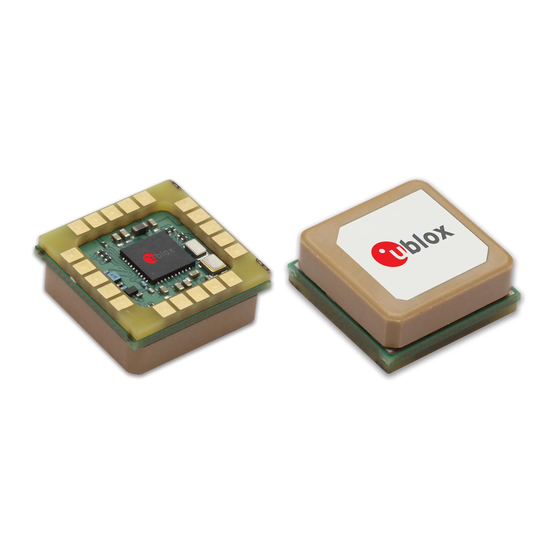
Top and bottom view
Advertisement
Table of Contents

Related Manuals for u-blox SAM-M8Q


Summary of Contents for u-blox SAM-M8Q
- Page 1 Hardware Integration Manual Abstract This document describes the hardware features and specifications of the SAM-M8Q patch antenna module, which features the u-blox M8 concurrent GNSS engine with reception of GPS, GLONASS, Galileo and QZSS signals. Top and bottom view www.u-blox.com...
- Page 2 The information contained herein is provided “as is” and u-blox assumes no liability for the use of the information. No warranty, either express or implied, is given, including but not limited, with respect to the accuracy, correctness, reliability and fitness for a particular purpose of the information.
-
Page 3: Preface
Preface u-blox Technical Documentation As part of our commitment to customer support, u-blox maintains an extensive volume of technical documentation for our products. In addition to our product-specific technical data sheets, the following manuals are available to assist u-blox customers in product design and development. -
Page 4: Table Of Contents
SAM-M8Q - Hardware Integration Manual Contents Preface ..........................3 Contents ..........................4 Hardware description ....................5 Overview ....................................5 Configuration ..................................5 Connecting power ................................... 5 Interfaces ....................................6 1.4.1 UART ....................................6 1.4.2 Display Data Channel (DDC) ..............................6 I/O pins .................................... -
Page 5: Hardware Description
The VCC pin provides the main supply voltage. During operation, the current drawn by the module can vary by some orders of magnitude, especially if enabling low-power operation modes. For this reason, it is important that the supply circuitry be able to support the peak power for a short time (see the SAM-M8Q Data Sheet [1] for specification). -
Page 6: Interfaces
DDC pins SDA and SCL have internal pull-up resistors to VCC_IO. For more information about the DDC implementation, see the u-blox 8 / u-blox M8 Receiver Description Including Protocol Specification [2]. For bandwidth information, see the SAM-M8Q Data Sheet [1] For timing parameters, consult the I2C-bus specification [6]. -
Page 7: I/O Pins
EXTINT is an external interrupt pin with fixed input voltage thresholds with respect to VCC_IO (see the SAM-M8Q Data Sheet [1] for more information). It can be used for wake-up functions in Power Save Mode on and for aiding. Leave open if unused, function is disabled by default. -
Page 8: Electromagnetic Interference On I/O Lines
SAM-M8Q - Hardware Integration Manual Electromagnetic interference on I/O lines Any I/O signal line with a length greater than approximately 3 mm can act as an antenna and may pick up arbitrary RF signals transferring them as noise into the GNSS receiver. This specifically applies to unshielded lines, in which the corresponding GND layer is remote or missing entirely, and lines close to the edges of the printed circuit board. -
Page 9: Design
Leave open if not used. SAFEBOOT_N Leave open. Table 1: SAM-M8Q Pinout 2.2 Minimal design This is a minimal setup for a SAM-M8Q GNSS antenna module: Figure 3: SAM-M8Q GNSS patch antenna design UBX-16018358 - R05 Production Information Design Page 9 of 23... -
Page 10: Footprint And Paste Mask
SAM-M8Q - Hardware Integration Manual 2.3 Footprint and paste mask The suggested solder mask openings are the same as the pad layout. Be sure to comply with special PCB layout design rules to ensure proper embedded antenna operation when the customer PCB is used as part of antenna. This requires solid ground plane around the module, see the section 2.60 for PCB layout suggestions. -
Page 11: Antenna
GNSS blocking caused by possible near-by wireless transmitters. The signal is further amplified by the internal Low Noise Amplifier (LNA) inside u-blox’s UBX-M8030 GNSS chip. Be sure to comply with special PCB layout design rules to ensure proper embedded antenna operation when the customer PCB is used as part of antenna. -
Page 12: Embedded Antenna Operation
Figure 7: 1.575 GHz typical free space radiation patterns Tall nearby components (h > 3 mm) should be placed at least 10 mm away from the SAM-M8Q module. An enclosure or plastic cover should have a minimum distance of 5 mm to the antenna. -
Page 13: Pcb Layout Suggestion
Easy to connect, but make sure all noisy lines / components are shielded or on inner layers Do not place any noisy parts close to SAM-M8Q, place them as far away as possible or on other side of PCB ... -
Page 14: Product Handling
3.1 Packaging, shipping, storage and moisture preconditioning For information pertaining to reels and tapes, Moisture Sensitivity levels (MSL), shipment and storage information, as well as drying for preconditioning see the SAM-M8Q Data Sheet [1] Population of Modules When populating the modules, make sure that the pick and place machine is aligned to the copper pins of the module and not to the module edge. - Page 15 Figure 9: Recommended soldering profile SAM-M8Q module must not be soldered with a damp heat process. Optical inspection After soldering the SAM‑M8Q antenna module, consider an optical inspection step to check whether: ...
- Page 16 Rework The SAM-M8Q module can be unsoldered from the baseboard using a hot air gun. When using a hot air gun for unsoldering the module, a maximum of one reflow cycle is allowed. In general, we do not recommend using a hot air gun because this is an uncontrolled process and might damage the module.
-
Page 17: Eos/Esd/Emi Precautions
EOS/ESD/EMI handling and protection measures. To prevent overstress damage at the RF_IN of your receiver, never exceed the maximum input power (see the SAM-M8Q Data Sheet [1]). Electrostatic discharge (ESD) Electrostatic discharge (ESD) is the sudden and momentary electric current that flows between two objects at different electrical potentials caused by direct contact or induced by an electrostatic field. -
Page 18: Electromagnetic Interference (Emi)
SAM-M8Q - Hardware Integration Manual GNSS positioning modules are sensitive to Electrostatic Discharge (ESD). Special precautions are required when handling. Electrical overstress (EOS) Electrical overstress (EOS) usually describes situations when the maximum input power exceeds the maximum specified ratings. EOS failure can happen if RF emitters are close to a GNSS receiver or its antenna. EOS causes damage to the chip structures. -
Page 19: Applications With Cellular Modules
Related documents for the absolute maximum power input at the GNSS receiver. See the GPS Implementation and Aiding Features in u-blox wireless modules [7]. Isolation between GNSS and cellular antenna In a handheld type design, an isolation of approximately 20 dB can be reached with careful placement of the antennas. - Page 20 Figure 12: Out-band interference signals Measures against out-band interference include maintaining a good grounding concept in the design and keep enough distance in between the antennas. See the GPS Implementation and Aiding Features in u-blox wireless modules [7] UBX-16018358 - R05 Production Information...
-
Page 21: Appendix
SAM-M8Q - Hardware Integration Manual Appendix A Glossary Abbreviation Definition ANSI American National Standards Institute CDMA Code Division Multiple Access Electromagnetic compatibility Electromagnetic interference Electrical Overstress Electrostatic Protective Area Electrostatic discharge Galileo European navigation system GLONASS Russian satellite system Ground... -
Page 22: Related Documents
SAM-M8Q - Hardware Integration Manual Related documents SAM-M8Q Data Sheet, Docu. No. UBX-16012619 u-blox 8 / u-blox M8 Receiver Description Including Protocol Specification (Public version), Docu. No. UBX-13003221 GNSS FW3.01 Release Notes (Public version), Docu. No. UBX-16000319 GPS Antenna Application Note, Docu. No. GPS-X-08014 GPS Compendium, Docu No. -
Page 23: Contact
SAM-M8Q - Hardware Integration Manual Contact For complete contact information, visit us at www.u-blox.com u-blox Offices North, Central and South America Headquarters Asia, Australia, Pacific Europe, Middle East, Africa u-blox America, Inc. u-blox Singapore Pte. Ltd. u-blox AG Phone: +1 703 483 3180...
Need help?
Do you have a question about the SAM-M8Q and is the answer not in the manual?
Questions and answers