
Subscribe to Our Youtube Channel
Related Manuals for Hytera RD620


Summary of Contents for Hytera RD620
- Page 1 Preface Thanks for your favor in our product. To derive optimum performance from the product, please read this manual and the Safety Information Booklet carefully before use.
- Page 2 Instructional Icons Caution: Indicates situations that could cause damage to your product or bodily injury. Note: Indicates tips that can help you make better use of your product. Term Explanation Voltage Standing Wave Ratio (VSWR) Voltage Standing Wave Ratio (VSWR) is a value that measures how well a load is impedance-matched to a source.
-
Page 3: Copyright Information
Copyright Information Hytera is the trademark or registered trademark of Hytera Communications Corporation Limited (the Company) in the People's Republic of China (PRC) and/or other countries or areas. The Company retains the ownership of its trademarks and product names. All other trademarks and/or product names that may be used in this manual are properties of their respective owners. - Page 4 Compliance with RF Exposure Standards Hytera's radio complies with the following RF energy exposure standards and guidelines: United States Federal Communications Commission, Code of Federal Regulations; 47 CFR § 1.1307, 1.1310 and 2.1091...
-
Page 5: Checking Items In The Package
1. Checking Items in the Package Please unpack carefully and check that all items listed below are received. If any item is missing or damaged, please contact your dealer. Repeater AC Power Cord Documentation Kit... -
Page 6: Product Introduction
2. Product Introduction Parts Part Name Part Name Front Panel Foot Pad Upper Cover Fan Mesh Enclosure Chassis... -
Page 7: Front Panel
Front Panel Part Name Part Name Power Indicator Slot B RX Indicator Digital Mode Indicator Alarm Indicator Analog Mode Indicator Fan Inlet Slot A TX Indicator D-SUB Data Interface Slot A RX Indicator RJ45 Data Interface Slot B TX Indicator Note: If the repeater is manufactured without internal duplexer, then part 8 will be an external duplexer RX port;... -
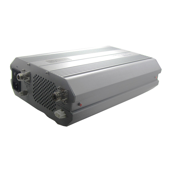
Page 8: Rear Panel
Rear Panel Part Name Part Name DC Power Inlet AC Power Inlet Fan Outlet AC Power Switch ANT/TX Antenna Connector (N-type Ground Terminal Female) Fuse Box RX Antenna Connector (N-type Female) -
Page 9: Status Indication
3. Status Indication LED indicators on the front panel indicate the following repeater status: LED Indicator LED Indicator Name Repeater Status Status Digital Mode Indicator Blue The repeater is operating in digital mode. Analog Mode Indicator Yellow The repeater is operating in analog mode. ... -
Page 10: Before Use
4. Before Use Instruction To ensure optimum performance and reliability of the repeater, please read the following instructions carefully. Operation Environment The repeater must be installed in a dry and well-ventilated place with ambient temperature of -30 ℃ to +60℃ and relative humidity of not more than 95%. Voltage Check Check whether the input voltage is within the operating voltage of the repeater (DC power supply: 13.6V ±15%;... - Page 11 1. Use the electric drill to drill three holes on the wall which align with that on the wall-mount bracket; 2. Put the expansion rubber plug into the drill holes; you can ignore this step if the wall is not a concrete wall;...
- Page 12 Step 2 To amount the repeater on the bracket, do as follows: 1. Align the hanging screws on the upper side of the repeater with the notch of the bracket and hang the repeater on the bracket; 2. Move the repeater side to side slightly to ensure the hanging screws reach the bottom of the notch.
-
Page 13: Basic Operation
5. Basic Operation Powering On/Off Powering On/Off Manually To power on, long press the AC Power Switch after connecting the power supply with the power adapter. To power off, long press the AC Power Switch. Auto Power On If the power of the adapter happens to be cut off or the power adapter runs out of the battery power when in use, the repeater will be powered off forcibly. - Page 14 6. Status Indication The LED indicators on the front panel indicate the following repeating status: LED Indicator Repeater Status Name Indication The repeater is Digital Mode LED Blue operating in digital Indicator mode. The repeater is Analog Mode LED Yellow operating in analog Indicator mode.
-
Page 15: Alarm Information
7. Alarm Information The repeater will have real-time detection of its status automatically. When the repeater is operating abnormally, the alarm indicator on the front panel will remain glowing red until all alarms are eliminated. When an alarm event occurs, you can diagnose and handle the problem via the RDAC application provided by us or contact your local dealer for technical support. -
Page 16: Troubleshooting
The group member is out of the Move towards the coverage of the coverage of the repeater. repeater. If the above solutions cannot fix the problems, or there are other questions, please contact Hytera or the dealer for more technical support. -
Page 17: Care And Cleaning
9. Care and Cleaning To guarantee optimal performance as well as a long service life of the repeater, please follow the tips below. Product Care Keep the repeater in good environmental conditions to ensure reliability. Do not place other equipment on top of the repeater to ensure optimal heat dissipation. ... -
Page 18: Optional Accessories
10. Optional Accessories Contact your local dealer for the optional accessories used with the product. Caution: Use the accessories specified by Hytera only. If not, Hytera shall not be liable for any losses or damages arising out of use of unauthorized accessories.
Need help?
Do you have a question about the RD620 and is the answer not in the manual?
Questions and answers