Table of Contents
Advertisement
Quick Links
142.0 mm
[5.59]
97.0 mm
[3.82]
1
6
12
7
CONNECTOR MATES
WITH DEUTCH
CONNECTOR #DTM-06-125A
158.2 mm
6.23
144.5 mm
5.69
PIN #1
INDICATED
1
6
12
7
47.1 mm
[1.85]
CONNECTOR MATES
WITH DEUTCH
CONNECTOR #DTM-06-125A
PLUS+1
Software
PLUS+1 Compliant
JS6000 XY-Axis
Joystick Function
Block
User Manual
2x 25.2 mm
[1.0]
TM
∅
2x
7.0
COM PLI AN T
[.28]
MOUNTING
DIRECTION
#2
LED INDICATOR
LIGHTS
51.6 mm
[2.03]
GUIDE
™
Advertisement
Table of Contents

Subscribe to Our Youtube Channel
Related Manuals for Sauer Danfoss JS6000

Summary of Contents for Sauer Danfoss JS6000
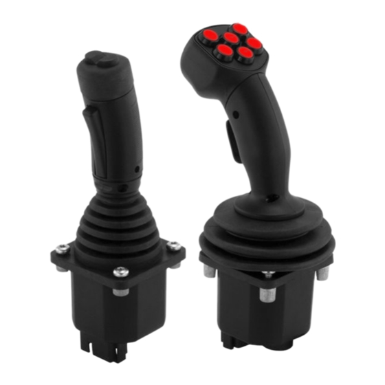
- Page 1 PLUS+1 GUIDE ™ Software PLUS+1 Compliant JS6000 XY-Axis Joystick Function Block User Manual 158.2 mm 6.23 144.5 mm 5.69 2x 25.2 mm 142.0 mm [1.0] [5.59] 97.0 mm [3.82] ∅ COM PLI AN T [.28] MOUNTING DIRECTION LED INDICATOR LIGHTS...
- Page 2 PLUS+1 Compliant JS6000 XY-Axis Joystick Function Block User Manual About this Manual To help you quickly find information in this manual, the material is divided into sections, Organization topics, subtopics, and details, with descriptive headings set in type. Section titles...
-
Page 3: Table Of Contents
PLUS+1 Compliant JS6000 XY-Axis Joystick Function Block User Manual Contents JS6000_XY Function Block ........................... 4 Overview..............................4 Inputs ................................4 Outputs ............................... 6 Connections and Signals Overview ....................6 Status and Fault Logic ..........................7 ... -
Page 4: Js6000_Xy Function Block
PLUS+1 Compliant JS6000 XY-Axis Joystick Function Block User Manual JS6000_XY Function Block Overview The JS6000_XY function block configures the output of a Sauer-Danfoss JS6000 XY-Axis joystick. This joystick has a base with three-point x and y-axes and a grip with up to eight pushbuttons. See: •... - Page 5 PLUS+1 Compliant JS6000 XY-Axis Joystick Function Block User Manual JS6000_XY Function Block JS6000_XY Function Block Inputs Input Type Range Description —— 0–5260 mV The voltage input to the X pin indicates the position of the joystick base on its x-axis.
-
Page 6: Outputs
PLUS+1 Compliant JS6000 XY-Axis Joystick Function Block User Manual JS6000_XY Function Block Outputs JS6000_XY Function Block Outputs Output Type Range Description Status Reports the function block’s status. This output uses the standard bitwise scheme described in the Basic Function Blocks Library User’s Manual. -
Page 7: Status And Fault Logic
PLUS+1 Compliant JS6000 XY-Axis Joystick Function Block User Manual JS6000_XY Function Block Status and Fault Logic The following table shows how: • The Status output indicates the calibration conditions of the inputs. • During calibration, the related Psn signal on the Out pin is zero. -
Page 8: Configuration Settings
PLUS+1 Compliant JS6000 XY-Axis Joystick Function Block User Manual JS6000_XY Function Block Configuration Settings Enter the JS6000_XY page to change the JS6000_XY function block’s configuration settings. When working with configuration settings for PLUS+1 compliant joysticks, note that: • Configuration inputs with a _Base suffix configure the joystick base. - Page 9 PLUS+1 Compliant JS6000 XY-Axis Joystick Function Block User Manual JS6000_XY Function Block JS6000_XY Function Block Configuration Settings Input Type Range Description LatchPFlt BOOL —— The function block sets a Status condition when it receives an invalid setup or calibration parameter.
- Page 10 PLUS+1 Compliant JS6000 XY-Axis Joystick Function Block User Manual JS6000_XY Function Block JS6000_XY Function Block Configuration Settings Input Type Range Description Dband_Mid —— 0–4999 The Dband_Mid (Deadband Middle) sets the width of a middle deadband. An input voltage within this band produces a 0% output.
-
Page 11: About Calibration Windows And Default Calibration Values
PLUS+1 Compliant JS6000 XY-Axis Joystick Function Block User Manual JS6000_XY Function Block About Calibration Windows and Default Calibration Values The following graph shows the relationship between the default calibration values and the windows in which the function block captures calibration values during autocalibration. - Page 12 PLUS+1 Compliant JS6000 XY-Axis Joystick Function Block User Manual JS6000_XY Function Block • During autocalibration, an input voltage must be between: − 250–750 mV to be captured as a CalLow calibration value. − 2250–2750 mV to be captured as CalMid calibration value.
-
Page 13: About Calibration Values And Deadbands
PLUS+1 Compliant JS6000 XY-Axis Joystick Function Block User Manual JS6000_XY Function Block About Calibration Values and Deadbands The following graph shows the: • Formulas used by the function block to calculate high, middle, and low deadband width. • Relationship between the calibration values captured during autocalibration and the width of the deadbands. - Page 14 PLUS+1 Compliant JS6000 XY-Axis Joystick Function Block User Manual JS6000_XY Function Block • An input voltage that falls within the: − Dband_Low deadband produces a -100% output from the function block. − Dband_Mid deadbands produces a 0% output from the function block.
-
Page 15: Mc Controller-Input Configuration
PLUS+1 Compliant JS6000 XY-Axis Joystick Function Block User Manual JS6000_XY Function Block MC Controller—Input Configuration If you have an SC controller, see SC Controller—Input Configuration on page 18. You can route the voltage needed by a joystick input though: •... -
Page 16: Mc Controller-How To Configure An Anin
PLUS+1 Compliant JS6000 XY-Axis Joystick Function Block User Manual JS6000_XY Function Block MC Controller—How to Configure an AnIn 1. In the GUIDE template, enter the Inputs page. 2. Enter the AnIn page that routes voltage the input. 3. Delete the route as shown in the preceding figure. -
Page 17: Mc Controller-How To Configure A Digan
PLUS+1 Compliant JS6000 XY-Axis Joystick Function Block User Manual JS6000_XY Function Block MC Controller—How to Configure a DigAn 1. In the GUIDE template, enter the Inputs page. 2. Enter the DigAn page that routes voltage to the input. 3. Delete the route as shown in the preceding figure. -
Page 18: Sc Controller-Input Configuration
PLUS+1 Compliant JS6000 XY-Axis Joystick Function Block User Manual JS6000_XY Function Block SC Controller—Input Configuration If you have an MC controller, see MC Controller—Input Configuration on page 15. You can route the voltage needed by a joystick input though: •... -
Page 19: Sc Controller-How To Configure A Digan
PLUS+1 Compliant JS6000 XY-Axis Joystick Function Block User Manual JS6000_XY Function Block SC Controller—How to Configure a DigAn 1. In the GUIDE template, enter the Inputs page. 2. Enter the DigAn page that routes voltage to the input. 3. Delete the routes as shown in the preceding figure. -
Page 20: About Pushbutton Wiring
PLUS+1 Compliant JS6000 XY-Axis Joystick Function Block User Manual JS6000_XY Function Block About Pushbutton Wiring A pushbutton input can be wired to: • +5 VDC common sensor power. • Common sensor power ground. Pushbutton input wired to +5 VDC common sensor power Pushbutton input wired to common sensor power ground 11007142 ·... -
Page 21: Mc Controller-Pushbutton Input Configuration
PLUS+1 Compliant JS6000 XY-Axis Joystick Function Block User Manual JS6000_XY Function Block MC Controller—Pushbutton Input Configuration You can route a pushbutton input to a Btn pin on the function block through: • A DigIn on your controller. • An MFIn on your controller. -
Page 22: Mc Controller-How To Configure A Digin For A Ground-Activated Pushbutton Input
PLUS+1 Compliant JS6000 XY-Axis Joystick Function Block User Manual JS6000_XY Function Block MC Controller—How to Configure a DigIn for a Ground-Activated Pushbutton Input 1. In the GUIDE template, enter the Inputs page. 2. Enter the DigIn page that configures the pushbutton input. -
Page 23: Mc Controller-How To Configure A Digan For A +5 Vdc Activated Pushbutton Input
PLUS+1 Compliant JS6000 XY-Axis Joystick Function Block User Manual JS6000_XY Function Block MC Controller—How to Configure a DigAn for a +5 VDC Activated Pushbutton Input 1. In the GUIDE template, enter the Inputs page. 2. Enter the DigAn page that configures the pushbutton input. -
Page 24: Mc Controller-How To Configure A Digan For A Ground-Activated Pushbutton Input
PLUS+1 Compliant JS6000 XY-Axis Joystick Function Block User Manual JS6000_XY Function Block MC Controller—How to Configure a DigAn for a Ground-Activated Pushbutton Input 1. In the GUIDE template, enter the Inputs page. 2. Enter the DigAn page that configures the pushbutton input. -
Page 25: Mc Controller-How To Configure A Mfin For A +5 Vdc Activated Pushbutton Input
PLUS+1 Compliant JS6000 XY-Axis Joystick Function Block User Manual JS6000_XY Function Block MC Controller—How to Configure a MFIn for a +5 VDC Activated Pushbutton Input 1. In the GUIDE template, enter the Inputs page. 2. Enter the MFIn page that configures the pushbutton input. -
Page 26: Mc Controller-How To Configure A Mfin For A Ground-Activated Pushbutton Input
PLUS+1 Compliant JS6000 XY-Axis Joystick Function Block User Manual JS6000_XY Function Block MC Controller—How to Configure a MFIn for a Ground-Activated Pushbutton Input 1. In the GUIDE template, enter the Inputs page. 2. Enter the MFIn page that configures the pushbutton input. -
Page 27: Sc Controller-Pushbutton Input Configuration
PLUS+1 Compliant JS6000 XY-Axis Joystick Function Block User Manual JS6000_XY Function Block SC Controller—Pushbutton Input Configuration You can route a pushbutton input to a Btn pin on the function block through: • A DigAn on your controller. • An MFIn on your controller. -
Page 28: Sc Controller-How To Configure A Digan For A Ground-Activated Pushbutton Input
PLUS+1 Compliant JS6000 XY-Axis Joystick Function Block User Manual JS6000_XY Function Block SC Controller—How to Configure a DigAn for a Ground-Activated Pushbutton Input 1. In the GUIDE template, enter the Inputs page. 2. Enter the DigAn page that configures the pushbutton input. -
Page 29: Sc Controller-How To Configure A Mfin For A +5 Vdc Activated Pushbutton Input
PLUS+1 Compliant JS6000 XY-Axis Joystick Function Block User Manual JS6000_XY Function Block SC Controller—How to Configure a MFIn for a +5 VDC Activated Pushbutton Input 1. In the GUIDE template, enter the Inputs page. 2. Enter the MFIn page that configures the pushbutton input. -
Page 30: Sc Controller-How To Configure A Mfin For A Ground-Activated Pushbutton Input
PLUS+1 Compliant JS6000 XY-Axis Joystick Function Block User Manual JS6000_XY Function Block SC Controller—How to Configure a MFIn for a Ground-Activated Pushbutton Input 1. In the GUIDE template, enter the Inputs page. 2. Enter the MFIn page that configures the pushbutton input. -
Page 31: About The Para Input
PLUS+1 Compliant JS6000 XY-Axis Joystick Function Block User Manual JS6000_XY Function Block About the Para Input Use the Para input to apply a common set of parameters to multiple function blocks. The preceding figure shows a Parameters page that outputs common, shared parameters to identical function blocks. - Page 32 PLUS+1 Compliant JS6000 XY-Axis Joystick Function Block User Manual JS6000_XY Function Block You create this Parameters page yourself. How you implement parameter sharing determines the inputs, outputs, contents, and name of this page. The preceding figure shows the changes made to a JS6000_XY page to enable this page to accept common parameters through its Para input.
-
Page 33: About The Name Space Feature
PLUS+1 Compliant JS6000 XY-Axis Joystick Function Block User Manual JS6000_XY Function Block About the Name Space Feature If you use this function block more than once in an application, you must change each function block’s Name Space value to avoid compiler errors. - Page 34 Products we offer: Sauer-Danfoss is a global manufacturer and supplier of high- quality hydraulic and electronic components. We specialize in • Bent Axis Motors providing state-of-the-art technology and solutions that excel in • Closed Circuit Axial Piston Pumps the harsh operating conditions of the mobile off-highway market. Building on our extensive applications expertise, we work closely and Motors with our customers to ensure exceptional performance for a broad...
Need help?
Do you have a question about the JS6000 and is the answer not in the manual?
Questions and answers