Advertisement
Table of Contents
- 1 Table of Contents
- 2 Warning Decal Placement
- 3 Important Precautions
- 4 Before You Begin
- 5 Part Identification Chart
- 6 Assembly
- 7 How to Use the Elliptical
- 8 Fcc Information
- 9 Maintenance and Troubleshooting
- 10 Exercise Guidelines
- 11 Part List
- 12 Exploded Drawing
- 13 Ordering Replacement Parts
- 14 Limited Warranty
- Download this manual
nordictrack.com
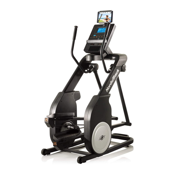
Model No. NTEL71315.3
Serial No.
Write the serial number in the space
above for reference.
ACTIVATE YOUR
WARRANTY
To register your product and
activate your warranty today,
go to my.nordictrack.com.
CUSTOMER CARE
For service at any time, go to
nordictrackservice.com.
Or call 1-800-TO-BE-FIT
(1-800-862-3348)
Mon.–Fri. 6 a.m.–6 p.m. MT
Sat. 8 a.m.–12 p.m. MT
Please do not contact the store.
CAUTION
Read all precautions and
instructions in this manual before
using this equipment. Keep this
manual for future reference.
Serial
Number
Decal
USER'S MANUAL
Advertisement
Table of Contents


Need help?
Do you have a question about the FREESTRIDE and is the answer not in the manual?
Questions and answers
Where is the reset button on a nordictrack freestride fs5i ellipital trainer?
The reset button on a NordicTrack Freestride FS5i elliptical trainer is located in a pinhole, most likely found on one of the sides or on the back of the console.
This answer is automatically generated
Where power adapter is plugged in on freestride fs5i. What is the name of that part?
The context does not specify the exact location where the power adapter is plugged in on the NordicTrack Freestride FS5i.
This answer is automatically generated