Table of Contents
Advertisement
Quick Links
The content in this manual has been carefully prepared and is believed to be accurate,
User's Manual
but no responsibility is assumed for inaccuracies.
For
Leadshine reserves the right to make changes without further notice to any products
herein to improve reliability, function or design. Leadshine does not assume any
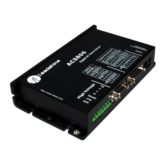
ACS806
liability arising out of the application or use of any product or circuit described
herein; neither does it convey any license under its patent rights of others.
Digital AC Servo Drive
Leadshine's general policy does not recommend the use of its products in life
support or aircraft applications wherein a failure or malfunction of the product may
Revision 1.0
directly threaten life or injury. According to Leadshine's terms and conditions of
©2009 All Rights Reserved
sales, the user of Leadshine's products in life support or aircraft applications
Attention: Please read this manual carefully before using the drive!
assumes all risks of such use and indemnifies Leadshine against all damages.
3/F, Block 2, Nanyou Tianan Industrial Park, Nanshan Dist, Shenzhen, China
©2009 by Leadshine Technology Company Limited.
Tel: (86)755-26434369
Fax: (86)755-26402718
URL:
www.leadshine.com
E-Mail:
sales@leadshine.com
All Rights Reserved
Advertisement
Table of Contents

Related Manuals for Leadshine Technology ACS806


Summary of Contents for Leadshine Technology ACS806
- Page 1 Attention: Please read this manual carefully before using the drive! assumes all risks of such use and indemnifies Leadshine against all damages. 3/F, Block 2, Nanyou Tianan Industrial Park, Nanshan Dist, Shenzhen, China ©2009 by Leadshine Technology Company Limited. Tel: (86)755-26434369 Fax: (86)755-26402718 URL: www.leadshine.com...
-
Page 2: Table Of Contents
ProTuner Installation ..................19 Connector Configuration..................4 Hardware Configurations before Tuning............23 General Information ..................4 ProTuner for the ACS806 at Startup Window ..........24 More about I/O Signals ................6 Introduction to ProTuner for the ACS806 ..........25 ENA, PUL, DIR Input Circuits and Connections..........7 Communication Setup ................26 RL, FL Input Circuits and Connections..............8... -
Page 3: Introduction, Features And Applications
T_Speed_Par tab ..................45 Introduction CurveSetting tab..................46 Digital Scope Window................47 Leadshine's fully digital AC servo drive ACS806 is developed with 32-bit DSP based on advanced control algorithm. Since its input commands are PUL/DIR Error Check Window..................47 7.Using Tips .......................49 signals, the users can upgrade stepping drives to the ACS806 without changing Change PPR by Electronic Gear................49... -
Page 4: Applications
R1.5[ 0.059] 97[ 3.819] 50[ 1.969] 2. Specifications and Operating Environment 3[ 0.118] 22[ 0.866] Electrical Specifications (T = 25℃/77℉) ACS806 150[5.906] Parameters Min. Typical Max. Unit 32[ 1.260] Peak output current 3[ 0.118]... -
Page 5: Connections
Encoder channel B+ output 3. Connections Encoder channel B- output Encoder channel Z+ output Connector Configuration Encoder channel Z- output General Information SGND Signal ground Halls & Encoder Connector Digital & Analog I/O Connector Signal Description Signal Description Encoder channel A+ input ENA+ Enable signal input + Encoder channel B+ input... -
Page 6: More About I/O Signals
ENA, PUL, DIR Input Circuits and Connections Signal Description The ACS806 has 3 differential logic inputs to accept Enable, Pulse and Direction Enable input signal. This signal used for enabling/disabling the drive. High level control signals. These inputs are isolated to minimize or eliminate electrical noises ENA+/ENA- for enabling the drive and low level for disabling the drive. -
Page 7: Rl, Fl Input Circuits And Connections
Pend, ALM Output Circuits and Connections Figure 5: Output circuit and connection for Pend and ALM connections to controller with Common-Anode outputs Figure 3: A+, A-, B+, B-, Z+, Z- Output Circuit RL, FL Input Circuits and Connections Recommend using the +5V supply output pin Digital & Analog I/O for FL/RL input. Figure 6: A+, A-, B+, B-, Z+, Z- output circuit Figure 4: Input circuit and connections for RL and FL Tel: (86)755-26434369... -
Page 8: Encoder And Hall Sensor Connections
Note that twisted-pair shielded cabling provides the best immunity in electrically noisy environments. The ACS806 has the +5V power to supply the encoder & hall sensor. If the encoder and hall sensor drains less than 100mA, the ACS806 can supply them directly, and connect it as Figure 7. -
Page 9: Servo Setup
There are some modules which can output signals both for encoder and hall sensor. Please assemble the selected module according to its factory manual. Leadshine also offer ACM series AC servo motors for matching the ACS806. Please use shielded cables and separate encoder signal cable from interference sources, such as motor wires and power wires at least 5 cm. -
Page 10: Selecting Supply Voltage
Both signal cables and power cables Prepare a controller with pulse and direction signals. However, the ACS806 has a should be of the twisted and shielded type. Differential signal wires should be twisted built-in motion controller for self-test and Servo Tuning. -
Page 11: System Grounding
If the red LED is off and the motor is normal, then you can start to tune the servo the ACS806 drive. The distance between the DC power supply of the drive and the with selected tool. PC based tuning software ProTuner and handheld small servo drive itself should be as short as possible since the cable between the two is a source tuning unit STU are available for the ACS806. -
Page 12: Pc Window Based Tuning Using Protuner
6. PC window based Tuning Using ProTuner Figure 11: Step and impulse responses As mentioned in previous contents, the ACS806 is a digital servo drive and its input Introduction to ProTuner command is PUL/DIR signal. In other words, step response just exists in each step command signal. - Page 13 Choose “I agree to the terms of this license agreement” and click Next to continue /Windows XP. And the selected PC should have 1 serial port at least for communicating with the drive. installation. The user can enter user’s information in the following window. See Double click “ProTuner_All_Setup_V1.0.exe”...
-
Page 14: Hardware Configurations Before Tuning
Hardware Configurations before Tuning Figure 17: Installation information summarization ProTuner uses PC RS232 port to communicate with the ACS806. The ACS806 has a RJ-11 connector in which a special RS232 cable is connected to PC RS232 port. Before opening ProTuner to tune the ACS806, the following configuration must be Tel: (86)755-26434369 Website: www.leadshine.com... -
Page 15: Protuner For The Acs806 At Startup Window
Status Bar ProTuner for the ACS806 at Startup Window Power on the ACS806. The green LED indicator should be on and the motor shaft should be locked if the servo system is OK. Please refer to the protection functions Figure 22: Main window of ProTuner for the ACS806 Tel: (86)755-26434369 Website: www.leadshine.com... -
Page 16: Communication Setup
Set the Encoder Lines according to encoder specification. The input number should be 4 times of the actual encoder lines/resolution since the ACS806 decodes the encoder signals in X4 mode (ie. 10000 for 2500 lines encoder). Figure 25: Software configuration before Tuning... - Page 17 Begin to Overshoot the drives with Leadshine’s ACM series servo motors. If you use the ACS806 with AC servo motors from other manufacturers, the current loop tuning may be needed.
-
Page 18: Position Loop Tuning
Feedforward gain can be added to improve tracking performance (i.e. minimize the difference between commanded and actual position). The velocity loop is disabled in current version ACS806, and it adopts Position around Current (Torque) mode. Position around Torque: This mode is most common in point-to-point applications, where actual motion between start and end point is not very critical. -
Page 19: Start To Tune
Critically Damped response. Figure 32: Digital Scope settings for the tuning As mentioned above, the ACS806 adopts position around current (torque) mode, and when tuning position around the current loop, a high derivative gain may be necessary on top of both proportional and integral gains. - Page 20 Figure 34: Position following error curve and velocity curve (Kp=800, Ki=0 and Kd=800) Figure 33: Position following error curve and velocity curve (Kp=800, Ki=0 and Kd=200) It’s very easy to see from the velocity curve (Green line) that the system is under damped.
- Page 21 Although a smooth velocity curve have been gotten in Figure 35, we can see that the position following error is still too large to accept. And this can be improved by increasing Ki value. See Figure 36. However, we can see the system response in Figure 35 is already Over Damped, namely too much damping has caused the response to be sluggish.
- Page 22 Increase Kd can reduce velocity overshoot, and get a better velocity curve in as shown in Figure 39. Figure 40: Position following error curve and velocity curve (Kp=1500, Ki=200 and Kd=1200) Figure 39: Position following error curve and velocity curve (Kp=1500, Ki=100 and Kd=1200) Since position following error is still large during constant speed period in Figure 39, we try to increase Ki to improve system’s performances.
- Page 23 Increasing Kp a little and reducing Ki to 350 can achieve a faster response with little overshoot, namely get a response close to Critically Damped response. See Figure Tuning servo systems formed by ACS806 drives can be summarized as the 43. Remember to download the parameter settings to the drive’s EEPROM when following rules.
-
Page 24: Upload And Download Data
ProTuner offers a tool to save all the configuration data on harddisk. This tool is very useful when building machines with same motors and other components. Select A built-in EEPROM in the ACS806 is used to save the configuration data. Every Option->Archives, the upload and download window will appear as figure 45. To time when you finish configuration or get satisfied parameters after tuning, don’t... -
Page 25: Control Signal Input Mode
Control Signal Input Mode In InputMode tab of Position Parameter window, the user can configure control signal input modes. DirectionDef: Direction Definition. Used to change the default movement direction to a specific input level (High or Low) in the DIR pins. Only active in PUL/DIR mode. -
Page 26: Curvesetting Tab
CurveSetting tab Digital Scope Window In Tuning->PositionLoop->CurveSetting tab, the user can choose curves displayed Digital monitor can display curves and dynamic values of different point of different in digital scope of Position Loop Tuning window and DigitalMonitor window, and curves. Click DigitalMonitor in the main menu will open this window. set their Trace Time. -
Page 27: Using Tips
ProTuner as shown in figure 50. You can set this parameter in the position Figure 49: Error check window tuning window by select Tuning->PositionLoop->P_parameter. For ACS806, the OverCurrent: Over-current Protection. Protection will be activated when actual PPR can be calculated by the following formula: continuous current exceeds 24A. -
Page 28: Position Following Error Limit
To improve reliability, the drive incorporates some built-in protection functions. The command and encoder feedback exceeds the setting limit value. To set the limit ACS806 uses one RED LED to indicate what protection has been activated. The value, please select Tuning->PositionLoop->P_parameter and find the Position periodic time of RED is 5 s (seconds), and how many times the RED turns on FollowingErrLimit edit box. -
Page 29: Limit Error Protection
Position following error protection Maximum Pulse Input Frequency Maximum Pulse Input Frequency is the highest frequency at which the drive can Figure 52: ACS806 accessories and connections interpret encoder feedback. To convert this frequency to RPM, use the following formula: Tel: (86)755-26434369 Website: www.leadshine.com... -
Page 30: More Information About Acs806 Accessories
Handheld configuration & tuning unit. Description Order Optional Accessory, one is enough to configure and tune multiple drives. Figure 53: ACS806 accessories and connections with extended cable More Information about ACS806 Accessories CABLE-STU ProTuner Special RS232 cable designed to setup communication between drive and... - Page 31 CABLE-DB26 CABLE-ACM-WINDING Connector and cable for control signals include ENA+,ENA-, PUL+, PUL-, Extended cable for power leads between the drive and Leadshine ACM series Description Description DIR+ and DIR-. AC servo motor. Optional Accessory, Leadshine provides 1.2m, 2.2m, 5m, 10m cable for user Order Standard Accessory, one driver needs at least one.
-
Page 32: Appendix
Send failed product to distributor in period, Leadshine will either, at its option, repair or replace products which proved your area or: Leadshine Technology Co., Ltd. Floor 3, Block 2, Tianan Industrial to be defective. -
Page 33: Contact Us
Contact Us China Headquarters Address: 3/F, Block 2, Nanyou Tianan Industrial Park, Nanshan District Shenzhen, China Web: http://www.leadshine.com Sales Hot Line: Tel: 86-755-2643 4369 (for All) 86-755-2641-7674 (for Asia, Australia, Africa areas) 86-755-2640-9254 (for Europe, America areas) Fax: 86-755-2640-2718 Email: sales@leadshine.com. Technical Support: Tel: 86 755-2641-8447 and 86-755-2647-1129 Fax: 86-755-2640-2718...