
Subscribe to Our Youtube Channel
Related Manuals for Leadshine Technology ACS306


Summary of Contents for Leadshine Technology ACS306
- Page 1 User’s Manual ACS306 Digital AC Servo Drive Revision 1.0 ©2010 All Rights Reserved Attention: Please read this manual carefully before using the drive!
-
Page 2: Table Of Contents
Contents Contents Cable Routing.....................12 Table of Contents Twisted Wires .....................12 Cable Shielding ..................13 1. Introduction, Features and Applications..............1 System Grounding..................13 Introduction ......................1 Power Supply Connection ................13 Features .........................1 5. Tuning the Servo ....................14 Applications ......................2 Testing the Servo ....................14 2. Specifications and Operating Environment..............2 Tuning the Servo ....................14 Electrical Specifications ..................2 Sequence Chart of Control Signals..............16... -
Page 3: Introduction, Features And Applications
A built-in controller can be used for testing and tuning. PC based and handheld configuration & tuning tools can meet different tuning environments or requirements. ACS306 Parameters The ACS306 can drive both DC brushless and AC servo motors. But it is more Min. Typical Max. -
Page 4: Mechanical Specifications
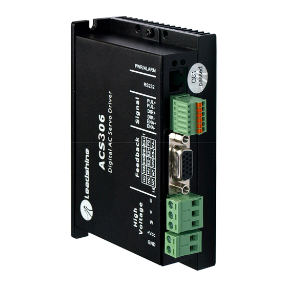
Mechanical Specifications (unit: mm[inch]) 3. Connections Connector Configuration General Information Feedback Signal Connector Signal Description Encoder channel A+ input Encoder channel B+ input Signal ground Hall sensor W input Hall sensor U input Ground terminal for shielded Reserve Reserve Hall sensor V input Figure 2-1: Mechanical specifications Not Connected Encoder channel A- input... -
Page 5: More About I/O Signals
Ground. Control Signal Connections RS232 receive. Not connected The ACS306 has 3 differential logic inputs to accept Enable, Pulse and Direction High Voltage Connector control signals and 1 OC (open collector) output for alarm (fault) output. These Signal Description... -
Page 6: Alarm Signal Connections
The ACS306 can accept both incremental encoder and hall effect sensor inputs for motor shaft position feedbacks. Note that twisted-pair shielded cabling provides the best immunity in electrically noisy environments. Figure 3-6: RS232 interface connection The ACS306 has the +5V power to supply the encoder & hall sensor. If the encoder... -
Page 7: Typical Connections
Typical Connections 4. Servo Setup A typical connection of the ACS306 is shown as Figure 3-7. Please consult “Control Signal Connections” and “Encoder and Hall Sensor Connections” for more Before you start the servo, you should follow the below steps. -
Page 8: Prepare Power Supply
Both signal cables and power cables Prepare a controller with pulse and direction signals. However, the ACS306 has a should be of the twisted and shielded type. Differential signal wires should be twisted built-in motion controller for self-test and Servo Tuning. -
Page 9: Cable Shielding
NEVER connect power and ground in the wrong direction, because it will damage tuning unit STU are available for the ACS306. the ACS306 drive. The distance between the DC power supply of the drive and the Tuning the Servo drive itself should be as short as possible since the cable between the two is a source A servo system is error-driven. -
Page 10: Sequence Chart Of Control Signals
Figure 5-1: Step and impulse responses In order to avoid some fault operations and deviations, PUL, DIR and EN should As mentioned in previous contents, the ACS306 is a digital servo drive and its input abide by some rules, shown as figure 5-2. -
Page 11: Protection Functions
To improve reliability, the drive incorporates some built-in protection functions. The the drive will be damaged instantly. ACS306 uses one RED LED to indicate what protection has been activated. The Protection Indications periodic time of RED is 5 s (seconds), and how many times the RED turns on indicates what protection has been activated. -
Page 12: Motor Speed Calculation
(max) × EncoderLin Leadshine Technology Co., Ltd. warrants its products against defects in materials Motor Speed Calculation and workmanship for a period of 12 months from shipping date. During the warranty period, Leadshine will either, at its option, repair or replace products which proved The motor speed can be calculated as the following formula: to be defective.
Need help?
Do you have a question about the ACS306 and is the answer not in the manual?
Questions and answers