Table of Contents
Advertisement
Quick Links
The content in this manual has been carefully prepared and is believed to be accurate,
but no responsibility is assumed for inaccuracies.
User's Manual
Leadshine reserves the right to make changes without further notice to any products
For
herein to improve reliability, function or design. Leadshine does not assume any
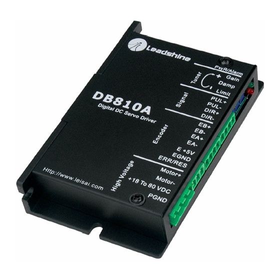
DB810A
liability arising out of the application or use of any product or circuit described
herein; neither does it convey any license under its patent rights of others.
Leadshine's general policy does not recommend the use of its products in life
Digital DC Servo Driver
support or aircraft applications wherein a failure or malfunction of the product may
directly threaten life or injury. According to Leadshine's terms and conditions of
Version 1.0
sales, the user of Leadshine's products in life support or aircraft applications
©2000 All Rights Reserved
assumes all risks of such use and indemnifies Leadshine against all damages.
Attention: Please read this manual carefully before using the driver!
©2000 by Leadshine Technology Company Limited.
Floor 3, Block 2, Nanyou Tianan Industry Park, Nanshan Dist, Shenzhen, China
Tel: (86)755-26434369
Fax: (86)755-26402718
All Rights Reserved
URL:
www.leadshine.com
E-Mail:
sales@leadshine.com
Advertisement
Table of Contents

Related Manuals for Leadshine Technology DB810A


Summary of Contents for Leadshine Technology DB810A
- Page 1 Leadshine against all damages. Attention: Please read this manual carefully before using the driver! ©2000 by Leadshine Technology Company Limited. Floor 3, Block 2, Nanyou Tianan Industry Park, Nanshan Dist, Shenzhen, China...
-
Page 2: Table Of Contents
Prepare Power Supply ..................8 Regulated or Unregulated Power Supply ............ 8 Selecting Supply Voltage................8 Prepare Controller ....................8 Initialize the DB810A ..................9 System Connections and Noise Prevention ............9 Wire Gauge....................10 Cable Routing.................... 10 Twisted Wires.................... 10 Cable Shielding .................. -
Page 3: Introduction, Features And Applications
DB810A are better than those of digital AC servo systems in velocity, precision, noise, stability, or at least as good as those of digital AC servo systems. However, the cost of the DB810A stays at the price line of stepping driver, namely far lower than those of AC servo drivers. -
Page 4: Operating Environment And Parameters
Control Signal Connections The DB810A can accept differential and single-ended inputs (including Cooling Natural cooling or forced cooling open-collector and PNP output). The DB810A have 2 optically isolated logic inputs Environment Avoid dust, oil fog and corrosive gases Ambient Temperature 0 º... -
Page 5: Encoder Connections
Figure 4: Connections to differential control signal Typical Connections Encoder Connections Two typical connections of the DB810A are shown as Figure 9 and Figure 10. The DB810A can accept encoder input from either differential or single-ended Please consult “Control Signal Connections” and “Encoder Connections” for more encoders. -
Page 6: Servo Setup
Selecting Supply Voltage 4. Servo Setup The DB810A can actually operate within +18V to +80VDC, including power input fluctuation and back EMF voltage generated by motor coils during motor shaft Before you start the servo, you can follow the below steps. -
Page 7: Initialize The Db810A
Initialize the DB810A Wire Gauge The DB810A use three potentiometers to tune the current Limit, the Gain and the The smaller wire diameter (lower gauge), the higher impedance. Higher impedance Damp. See Figure 11. These potentiometers are 10-turn potentiometers. CW wire will broadcast more noise than lower impedance wire. -
Page 8: System Grounding
NEVER connect power and ground in the wrong direction, because it will damage ramp the speed up to see if the motor runs. It should run clockwise with a logical “1” the DB810A driver. The distance between the DC power supply of the drive and the on the direction input. - Page 9 OVER DAMPED state. When we tune a servo, we are trying to achieve the fastest (including TEST point and GND point) is set inside of the DB810A. See Figure 14. response with little or no overshoot, namely get a CRITICALLY DAMPED When there is no position error, the voltage should be 2.5V.
-
Page 10: Adjusting Gain And Damp Coefficients
Although the steady state position error of the DB810A servo system is usually can be eliminated to ±1 count (see Figure 16.), here we assumed that the acceptable SETTLING BAND is ±(|ΔY(1)|/0.01953) = ±(0.0563/0.01953) ≈... - Page 11 When you encounter UNDER DAMPED response, you should decrease Gain or increase Damp to get a CRITICALLY DAMPED response, like Figure 17 below. Here the motor rapidly returns to the set point with little or no overshoot and the minimal SETTLING TIME. In Figure 17 (b) the SETTLING TIME is 13.30ms much faster than that of Figure 15 (b).
-
Page 12: Using Tips
Limit setting is active, the motor position may fall behind the command position because of insufficient torque. Alarm LED Normally when the DB810A is first powered up, it will be necessary to push the (a) Max error (b) Steady state error momentary switch to START servo for 2 seconds. -
Page 13: Changing Default Motor Direction
This port functions as an error output and as a servo start/restart input. When first testing the DB810A or it is not necessary to read the state of the error output, ERR/RES port can be connected to E +5V port. -
Page 14: Appendix
Send failed product to distributor in to be defective. your area or: Leadshine Technology Co., Ltd. Floor 3, Block 2, Tianan Industry Park, Nanshan Dist, Shenzhen, China. Also enclose information regarding the EXCLUSIONS circumstances prior to product failure.
Need help?
Do you have a question about the DB810A and is the answer not in the manual?
Questions and answers