Table of Contents
Advertisement
Quick Links
The content in this manual has been carefully prepared and is believed to be accurate,
but no responsibility is assumed for inaccuracies.
User's Manual
Leadshine reserves the right to make changes without further notice to any products
For
herein to improve reliability, function or design. Leadshine does not assume any
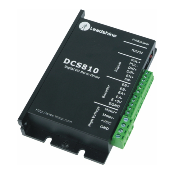
DCS810
liability arising out of the application or use of any product or circuit described
herein; neither does it convey any license under its patent rights of others.
Leadshine's general policy does not recommend the use of its products in life
Digital DC Servo Driver
support or aircraft applications wherein a failure or malfunction of the product may
directly threaten life or injury. According to Leadshine's terms and conditions of
Revision 1.0
sales, the user of Leadshine's products in life support or aircraft applications
©2008 All Rights Reserved
assumes all risks of such use and indemnifies Leadshine against all damages.
Attention: Please read this manual carefully before using the driver!
©2008 by Leadshine Technology Company Limited.
3/F, Block 2, Nanyou Tianan Industrial Park, Nanshan Dist, Shenzhen, China
Tel: (86)755-26434369
Fax: (86)755-26402718
All Rights Reserved
URL:
www.leadshine.com
E-Mail:
sales@leadshine.com
Advertisement
Table of Contents

Related Manuals for Leadshine Technology DCS810


Summary of Contents for Leadshine Technology DCS810
- Page 1 Leadshine against all damages. Attention: Please read this manual carefully before using the driver! ©2008 by Leadshine Technology Company Limited. 3/F, Block 2, Nanyou Tianan Industrial Park, Nanshan Dist, Shenzhen, China Tel: (86)755-26434369...
-
Page 2: Table Of Contents
Contents Contents Cable Routing ................... 12 Table of Contents Twisted Wires.................... 12 Cable Shielding ..................13 1. Introduction, Features and Applications..............1 System Grounding..................13 Introduction ......................1 Power Supply Connection................. 13 Features ........................ 1 5. Tuning the servo....................14 Applications ...................... -
Page 3: Introduction, Features And Applications
AC servo systems. However, Over-current, over-voltage, under-voltage, phase error, encoder error, position the cost of the DCS810 stays at the price line of stepping driver, namely far lower following error protections than those of AC servo drivers. -
Page 4: Specifications And Operating Environment
PUL- Pulse control signal (-). Electrical Specifications (T = 25℃) Direction control signal (+). See more information about DIR in DIR+ “More about PUL/DIR/EN Signals” section. DCS810 DIR- Direction control signal (-). Parameters Enable control signal (+). Min. Typical Max. -
Page 5: More About Pul/Dir/En Signals
1.0μs. Series connect resistors for current-limiting PUL- open-collector and PNP output). The DCS810 has 2 optically isolated logic inputs to when using +12V or +24V control signals. accept line driver control signals. These inputs are isolated to minimize or eliminate DIR signal: In single-pulse mode, this signal has low/high voltage levels, representing two directions of motor rotation(set by inside R33 and R37);... -
Page 6: Encoder Connections
B- lines are pulled up internally to +2.5V). Note that twisted-pair shielded cabling provides the best immunity in electrically noisy environments. If the encoder drains less than 50mA, the DCS810 can supply the encoder directly, Figure 3: Connections to open-collector control signal (common-anode) and connect it as Figure 6 or Figure 7. -
Page 7: Rs232 Interface Connection
RS232 Interface Connection Figure 10: RS232 interface connection Typical Connections Two typical connections of the DCS810 are shown as Figure 11 and Figure 12. Please consult “Control Signal Connections” and “Encoder Connections” for more information about controller and encoder connections. -
Page 8: Prepare Power Supply
Both signal cables and power cables Prepare a controller with pulse and direction signals. However, the DCS810 has a should be of the twisted and shielded type. Differential signal wires should be built-in motion controller for self-test and Servo Tuning. -
Page 9: Cable Shielding
NEVER connect power and ground in the wrong direction, because it will damage the DCS810 driver. The distance between the DC power supply of the drive and the with selected tool. ProTuner, EZ-Tuner and STU are available for the DCS810. -
Page 10: Tuning The Servo
4. If servo system is OVER DAMPED, then decrease Kd or increase Kp or Figure 13: Step and impulse responses As mentioned in previous contents, the DCS810 is a digital servo driver and its input Please see user’s manuals of those tuning tools for more detail about Servo Tuning. -
Page 11: Using Tips
Position Following Error Protection To improve reliability, the driver incorporates some built-in protection functions. The DCS810 uses one RED LED to indicate what protection has been activated. The When position following error reaches Position Following Error Limit parameter periodic time of RED is 5 s (seconds), and how many times the RED turns on setting in the driver, this protection will be activated. -
Page 12: Protection Indications
OBTAINING WARRANTY SERVICE Changing Default Motor Direction To obtain warranty service, a returned material authorization number (RMA) must The DCS810 will turn the motor in the CW direction when the direction input is be obtained from customer service at e-mail: tech@leadshine.com before returning “high”... -
Page 13: Shipping Failed Product
Please include a written description of the problem along with contact name and address. Send failed product to distributor in your area or: Leadshine Technology Co., Ltd. Floor 3, Block 2, Tianan Industrial Park, Nanshan Dist, Shenzhen, China. Also enclose information regarding the circumstances prior to product failure.
Need help?
Do you have a question about the DCS810 and is the answer not in the manual?
Questions and answers