Table of Contents
Advertisement
Quick Links
9049 Tyler Blvd. • Mentor, Ohio 44060
Phone (440) 974-8888 • Fax (440) 974-0165
Quality since 1946
Toll-Free Fax 800-841-8003 • buyersproducts.com
Installation Instructions
G9003
Gooseneck Retractable Ball Mount
Read These Installation Instructions
Completely Before Starting Installation
The retractable ball mount is a 2-5/16" hitch ball designed to
be mounted on a truck and positioned forwards and above
the rear axle. This device is specifically for towing goose-
neck trailers.
• Maximum Gross Vehicle Weight: 25,000 lbs.
• Ball Size: 2-5/16" diameter
• Vertical Load Capacity: 5,000 lbs.
The instructions following are for mounting the retractable
gooseneck ball in a pickup truck bed. Do not exceed the
towing vehicle's rated towing capacity.
Truck Bed Floor Cut-Out and
Mounting Location
1. The installed gooseneck hitch baIl should be centered
between the sides of the truck bed. The ball in raised posi-
tion should be in the center of the floor (between the sides)
and 2" to 6" forwards of the rear axle center line (see Fig. 1).
CAUTION: The ball must be positioned to allow adequate
clearance between the gooseneck trailer and the rear cor-
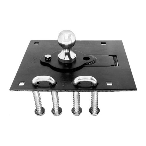
ners of the truck bumper. Adequate clearance between the
Fig. 1 Gooseneck Ball Assembly
gooseneck trailer and the rear of the truck cab must be pro-
vided. The preceding clearances should be checked with
the trailer center axis 90° to the truck center axis.
2. Identify and mark the pickup bed area where the center
of the hitch ball will be after installation.
3. An 8" x 11-1/2" template cut-out will be used to install
the gooseneck hitch ball. Refer to Fig. 2 to make sure of the
correct position of the 8" x 11-1/2" template cut-out. This will
allow for flush mounting of the folding hitch ball. CAUTION:
Check for all important truck components prior to drilling or
cutting the truck bed. Do not cut the brake lines or cables,
fuel lines, vents, electrical wiring, etc. If a cross member is
encountered interfering with the cut-out, move the assem-
bly fore or aft to clear the cross member. The center of the
ball must locate 2" to 6" forward of the rear axle centerline.
4. The 8" x 11-1/2" template cut-out should be offset to the
driver's side of the truck bed floor.
5. Cut 8" x 11-1/2" template outline on the floor of the truck bed.
6. The gooseneck hitch ball assembly must be supported
by the truck frame rails. The following two methods
Fig. 2 Gooseneck Ball Installation
provide for fabricating proper support structures for
frame attachment. Either method will be satisfactory:
—continued inside
Advertisement
Table of Contents

Subscribe to Our Youtube Channel
Related Manuals for Buyers G9003


Summary of Contents for Buyers G9003
-
Page 1: Installation Instructions
Phone (440) 974-8888 • Fax (440) 974-0165 Quality since 1946 Toll-Free Fax 800-841-8003 • buyersproducts.com Installation Instructions G9003 Gooseneck Retractable Ball Mount Read These Installation Instructions Completely Before Starting Installation The retractable ball mount is a 2-5/16" hitch ball designed to be mounted on a truck and positioned forwards and above the rear axle. - Page 2 Quality since 1946 Bed Plate Support Structure Method 4. Using the four square holes in the gooseneck ball assem- bly as guides, drill four 11/16" diameter holes through the Material to be provided by installer: bed plate and the truck bed. 1 - 26"...
- Page 3 Quality since 1946 H-Frame Support Structure Method WARNING: A steel bar frame is fabricated as shown in Fig. 6. Secure H-frame to truck frame with four 2" wide x 3/8" 1. Install gooseneck ball assembly in truck bed cut-out. thick steel angle brackets, using two per side as shown Insure raised ball is centered between truck bed side rails.
- Page 4 Normal wear is excluded. The sole responsibility of Buyers Products Co. under this warranty is limited to repairing or replacing any part or parts which are returned, prepaid, and are found to be defective by Buyers Products Co.
Need help?
Do you have a question about the G9003 and is the answer not in the manual?
Questions and answers