Pyxis LS-202 Operation Manual
General-purpose ultrasonic level sensor
Hide thumbs
Also See for LS-202:
- User manual (24 pages) ,
- User manual (22 pages) ,
- User manual (17 pages)
Table of Contents
Advertisement
Quick Links
Advertisement
Table of Contents

Subscribe to Our Youtube Channel
Related Manuals for Pyxis LS-202


Summary of Contents for Pyxis LS-202
- Page 1 LS-202 Level Sensor Operational Manual Version 1.2 December 2018...
- Page 2 A Repair Authorization Number (RA) must be obtained from Pyxis Technical Support before any product can be returned to the factory. Pyxis will pay freight charges to ship replacement or repaired products to the customer. The customer shall pay freight charges for returning products to Pyxis. Any product returned to the factory without an RA number will be returned to the customer.
-
Page 3: Table Of Contents
8.3. Parameter Setting via uPyxis Desktop 9. 4-20mA Output Setup 10. Output 4-20mA via BTA-100 Adaptor 10.1. Peripheral to Central Mode (LS-202 Connection to BTA-100) 10.2. Beacon to Observer Mode (LS-202 Connection to BTA-100) 11. Communication using Modbus RTU 12. Sensor Cleaning and Maintenance... -
Page 4: Introduction
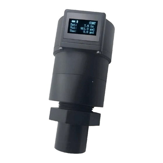
1. Introduction The Pyxis LS-202 is a general-purpose ultrasonic sensor. It provides continuous level measurement up to 78 inches (6.6 ft. or 2 m) with a 4-20 mA signal, RS485, and Bluetooth digital output. It can be configured via the uPyxis® app on mobile phones or computers. The sensor can be powered by 4 AA alkaline batteries or a 24 VDC external power supply. -
Page 5: Unpacking The Instrument
The LA-202 can be powered by four (4) AA alkaline batteries if a 24 VDC is not available. The measured level signal can be read by the uPyxis App via Bluetooth or transmitted to a controller via the Pyxis Bluetooth to 4-20mA Transmitter BTA-100. Do not use rechargeable nickel cadmium (NiCad) or rechargeable lithium batteries. - Page 6 O-ring is lying flat in the groove of the main sensor body. Failure to do so may result in water/moisture damage to the sensor. To prevent the LS-202 from accidently being turned on or off due to vibration, please firmly tighten the hex bolts.
-
Page 7: Ls-202 Wiring
4.2. LS-202 Wiring The LS-202 can also be powered by a 24V DC power supply and output the result with the 4-20mA output. When it is 24V powered, the battery set will stop powering the sensor. If the power ground terminal and the negative 4-20 mA terminal in the controller are internally connected (non-isolated 4-20mA input), it is unnecessary to connect the 4-20 mA negative wire (green) to the 4-20 mA negative terminal in the controller. -
Page 8: Instrument Overview
5.1. Function Buttons The Buttons on the top of the LS-202 (Figure 3) are used to select one of four display modes, one of three Bluetooth mode, and one of four measurement modes. These buttons are not used to set up the... - Page 9 The absence of Bluetooth sign represents the shutdown mode and that the Bluetooth communication is turned off. Power consumption in the peripheral mode is much higher than the Beacon mode. Please use the Beacon mode for a long-term Bluetooth connection if the LS-202 is on the battery power. Delivery Mode Button: Press the Power button twice to enter Delivery mode.
-
Page 10: Oled Display
Figure 4. Sensor Connection and Indicators 5.2. OLED Display The OLED display supports four display modes as shown in the following figures. Press the Display Mode button to switch modes. Figure 5. Mode 1, General Information... - Page 11 Figure 6. Mode 2, Level Display Figure 7. Mode 3, Remaining Volume Figure 8. Mode 4, Volume Consumed Figure 9. Device MAC Address, FCC ID, and ERROR Code...
- Page 12 Figure 10. System Time and Software Version (Note 1) Note 1: The system time will be reset to 2000-01-01 on every power-on operation. Please use uPyxis app to wireless connect the sensor to a phone or PC before the use. With the connection, the system time will be automatically set according to the phone or PC’s clock.
-
Page 13: Ls-202 Setup With Upyxis
6. LS-202 Setup with uPyxis Pyxis LS-202 has four modes Bluetooth modes: Peripheral mode, Beacon mode, Delivery mode, and Shutdown mode. Peripheral mode: Connected with another Bluetooth devices via uPyxis app, such as a smart phone, computer with Bluetooth USB adapter (PN: MA-NEB), or the BTA-100. -
Page 14: Ls-202 With Upyxis Mobile App
20 minutes before switching back to Beacon mode. Figure 13. Reading Volume and Full Volume Shutdown mode: Cannot be connected icon display is absent in OLED screen. 7. LS-202 with uPyxis Mobile App 7.1. Downloading uPyxis Mobile App Download uPyxis Mobile App from... -
Page 15: Connecting To Upyxis Mobile App
7.2. Connecting to uPyxis Mobile App Turn on Bluetooth on your mobile phone. (Do not pair the phone Bluetooth to the LS-202) Open uPyxis Mobile App. uPyxis App connects to the Meter and click on the LS-202 meter. When connected, Mobile App will default to the Overview screen. - Page 16 To set the parameters Click on Setting. Enter Installation Height, Tank Volume, and Max Level Height (Max Level Height must be less then Installation Height) then press to save. To verify your readings after setting your parameters click on Reading.
-
Page 17: Ls-202 With Upyxis Desktop App
Read Last (for last 100 readings) or Read Overview (for overview readings). To download records, press Export/Share. 8. LS-202 with uPyxis Desktop App 8.1. Downloading uPyxis Desktop App Download the latest version of uPyxis Desktop software package from: https://pyxis-lab.com/support-2/ This setup package will download and install the Microsoft .Net Framework 4.5 (if not installed on the PC before), the USB driver for the USB-Bluetooth adapter, the USB-RS485 adapter, the USB-RS485 adaptor, and the main uPyxis Desktop application. -
Page 18: Connecting To The Upyxis Desktop App
3. On uPyxis Desktop, click menu Device -> Connect via USB-Bluetooth as show in Figure 15. If the connection is successful, the LS-202 figure and its Serial Number will be displayed in the left pane of the uPyxis window as shown in Figure 16. -
Page 19: Parameter Setting Via Upyxis Desktop
8.3. Parameter Setting via uPyxis Desktop Click Setting to set the LS-202 parameters as show in Figures 16 - 18. The LS-202 sensor measures the distance between the liquid surface in the tank and the bottom sensor surface. Converting this... - Page 20 Figure 17. Illustration of Term and Tank Capacity Setup Figure 18. Installation Height, Max Height, and Sampling Interval...
- Page 21 Figure 19. Set button to save settings Definitions figures 17 – 19. ( After entering any setup parameter, click the button to confirm the setting.) • Volume Volume of the tank • Max Height Liquid level measured from the tank bottom as filled to rated capacity •...
- Page 22 Click Reading menu to display LS-202 real-time measurement data in a trend chart shown in figure 20 Figure 20. Level Trend Chart Click DataLog to enter DataLog screen. Then you can click on Read Overview Value Read Recent 100 Datalog to upload the historical measurement data as shown in figure 21.
-
Page 23: 20Ma Output Setup
Figure 22. Firmware Upgrade 9. 4-20mA Output Setup The 4-20mA output of the LS-202 is scaled as: 4 mA = (Tank is Empty) = (Level is 0) = (Distance is Installation Height), 20 mA = (Tank is Full) = (Level is maximum height) = (Distance is Installation – Maximum Height). -
Page 24: Output 4-20Ma Via Bta-100 Adaptor
(pairing), Observer (beacon reader), and Central. Reference the BTA-100 manual for details. The LS-202 sensor can be wirelessly connected to the BTA-100 in two ways as listed in the following table. The 4-20mA output from the BTA-100 adaptor can be wired to a controller per manual. -
Page 25: Beacon To Observer Mode (Ls-202 Connection To Bta-100)
Follow the following steps to pair the LS-202 sensor with the BTA-100 adapter. • Turn on the LS-202 and switch to the peripheral mode (Bluetooth mode indicator “P” on the LS- 202 screen). • Use the Bluetooth button to switch the BTA-100 to the Central mode (Bluetooth mode indicator “C”... -
Page 26: Communication Using Modbus Rtu
11. Communication using Modbus RTU The LS-202 can be configured as a Modbus slave device via RS-485. In addition to the level, volume, and distance, many operational parameters, including warning and error messages, are available via a Modbus RTU connection. - Page 27 • Reorient or relocate the receiving antenna. • Increase the separation between the equipment and receiver. • Connect the equipment into an outlet on a circuit different from that to which the receiver is connected. • Consult the dealer or an experienced radio/TV technician for help. Canada This device complies with Industry Canada license exempt RSS standard(s).
Need help?
Do you have a question about the LS-202 and is the answer not in the manual?
Questions and answers