Table of Contents

Related Manuals for Pyxis LSP Series


Summary of Contents for Pyxis LSP Series
- Page 1 LSP Series Submersible Pressure Level Sensor User Manual March 30, 2020 Rev. 3.01 Pyxis Lab, Inc. 1729 Majestic Dr. Suite 5 Lafayette, CO 80026 USA www.pyxis-lab.com © 2017 Pyxis Lab, Inc. Pyxis Lab Proprietary and Confidential...
-
Page 2: Table Of Contents
9 Sensor Maintenance and Precaution 9.1 Methods to Cleaning LSP Series Transducer ......10 Regulatory Approval... - Page 3 Pyxis Lab, Inc. Standard Limited Warranty Pyxis Lab warrants its products for defects in materials and workmanship. Pyxis Lab will, at its option, repair or replace instrument components that prove to be defective with new or remanufactured components (i.e., equivalent to new).
-
Page 4: Introduction
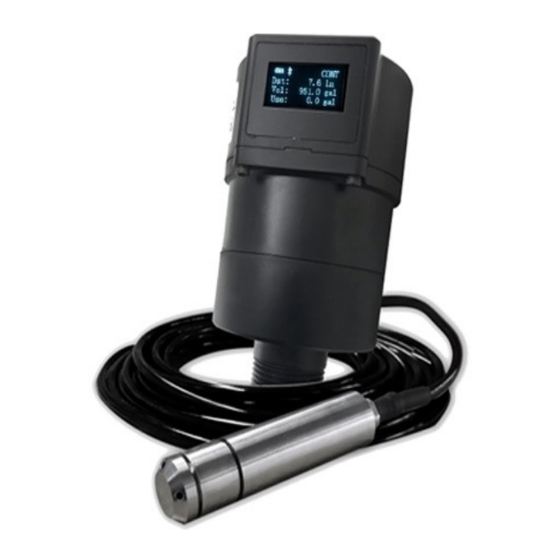
393 inch (32.8 ft or 10 m) with a 4-20mA analog and Bluetooth digital output. It can be configured via the Pyxis’s uPyxis® Mobile App or uPyxis® Desktop App. The sensor can be powered by 4 AA Li/SOCl batteries or a 24 VDC external power supply. -
Page 5: Specifications
Transducer Rating IP68 Regulation With Pyxis’s continuous improvement policy, these specifications are subject to change without notice. 3 Unpacking Instrument Remove the instrument and accessories from the shipping container and inspect each item for any damage that may have occurred during shipping. Verify that all accessory items are included. If any item is missing or damaged, please contact Pyxis Lab Customer Service at service@pyxis-lab.com. -
Page 6: Optional Accessories
These batteries are unique and available through Pyxis Lab (P/N: 50731). Typical battery life after replac- ing a new battery set is about 6 months with a 60 minute measurement interval. The LSP Series battery compartment is shown in Figure 3. -
Page 7: Tank Top And Mounting Bracket Installation
Failure to do so may result in water/moisture damage to the sensor. 5. Firmly tighten the hex bolts to prevent the LSP Series sensor from accidentally being turned on or off due to vibration. - Page 8 Figure 5. Display/Processor Module Dimension, inch (mm) The display/processor module of the LSP Series sensor can be installed to a 1-inch bulkhead fitting on the top of the tank. Alternatively, you may also use the LSP Series Mounting Bracket (P/N: 50770) for installations where top tank mount may be to too high for visual display verification.
-
Page 9: Wiring
5 Instrument Overview 5.1 Function Buttons The buttons on top of the LSP Series sensor (Figure 7) are used to select one of four display modes, one of three Bluetooth modes, and one of four measurement modes. NOTE The function buttons are not used to configure the sensor. - Page 10 Working Mode Button : This button cycles through the different measurement intervals pre-programmed into the LSP Series sensor. The current measurement interval is displayed on the top-right corner of the OLED screen: • CONT: Continuous measuring • 10s: Measurement every 10 seconds •...
-
Page 11: Oled Display
Figure 9. Display Mode 2: Level Figure 10. Display Mode 3: Remaining Volume Figure 11. Display Mode 4: Used Volume Figure 12. System Info Mode 1: ID’s and Error Code (EC) LSP Series User Manual service@pyxis-lab.com | +1 (866) 203-8397... -
Page 12: Display Symbol Glossary
The date/time will reset to 2000-01-01 00:00:00 on every power-on operation. When the LSP Series sensor is connected to a phone or PC via the uPyxis® App, the date/time will be automatically set according to the phone or PC’s clock. The wrong system date/time does not affect the sensor measurement function, but the time stamp in the data log will be incorrect. -
Page 13: Setup And Configuration With Upyxis® Mobile App
6.2 Connecting to uPyxis® Mobile App Turn on Bluetooth on your mobile phone (Do not pair the phone Bluetooth to the LSP Series sensor). Open uPyxis® Mobile App. Once the app is open the app will start to search for the sensor. When the uPyxis®... -
Page 14: Overview Screen
Figure 16. 6.4 Reading Screen The Reading screen displays the current volume of liquid remaining and liquid level over time. Figure 17. LSP Series User Manual service@pyxis-lab.com | +1 (866) 203-8397... -
Page 15: Settings Screen
6.5 Settings Screen The LSP Series sensor measures the hydrostatic pressure created by the liquid level in the tank. Convert- ing this measured pressure value to other parameters such as the tank level and the remaining liquid vol- ume in gallons requires the tank volume capacity, the tank maximum liquid height measured from the bottom of the tank to the liquid surface when filled to the rated capacity, and the density of the liquid. -
Page 16: Datalog Screen
6.6 Datalog Screen From the Datalog screen, you can view and download the data records of the LSP Series sensor. To view the records, press Read Records, then press either Read Overview, Read Last 100, or Read All. To download the records, press Export/Share. -
Page 17: Connecting To Upyxis® Desktop App
7.2 Connecting to uPyxis® Desktop App Connect the LSP Series sensor to a Windows computer using a Bluetooth/USB adapter (P/N: MA-NEB) ac- cording to the following steps: 1. Plug the Bluetooth/USB adapter into a USB port in the computer. 2. Hold the key on LSP Series sensor until the Bluetooth mode changes to Peripheral mode ( P). -
Page 18: Overview Screen
Figure 22. 7.4 Reading Screen The Reading screen displays the current liquid level and the liquid level over time. Figure 23. LSP Series User Manual service@pyxis-lab.com | +1 (866) 203-8397... -
Page 19: Setting Screen
7.5 Setting Screen The LSP Series sensor measures the hydrostatic pressure created by the liquid level in the tank. Convert- ing this measured pressure value to other parameters such as the tank level and the remaining liquid vol- ume in gallons requires the tank volume capacity, the tank maximum liquid height measured from the bottom of the tank to the liquid surface when filled to the rated capacity, and the density of the liquid. -
Page 20: Datalog Screen
LSP Series sensor for practical purposes. 8.2 Communication Using Modbus RTU The LSP Series sensor can be configured as a Modbus slave device via RS-485. In addition to the level and volume, many operational parameters, including warning and error messages, are available via a Modbus RTU connection. -
Page 21: Sensor Maintenance And Precaution
10 Regulatory Approval United States The LSP Series sensor has been tested and found to comply with the limits for a Class B digital device, pursuant to part 15 of the FCC Rules. These limits are designed to provide reasonable protection against harmful interference in a residential installation. -
Page 22: Contact Us
11 Contact Us Pyxis Lab, Inc 1729 Majestic Dr. Suite 5 Lafayette, CO 80026 USA www.pyxis-lab.com Phone: +1 (866) 203-8397 Email: service@pyxis-lab.com LSP Series User Manual service@pyxis-lab.com | +1 (866) 203-8397...
Need help?
Do you have a question about the LSP Series and is the answer not in the manual?
Questions and answers