Pyxis LS-200 User Manual
Ultrasonic level sensor
Hide thumbs
Also See for LS-200:
- User manual (17 pages) ,
- User manual (22 pages) ,
- Quick start up manual (5 pages)
Table of Contents
Advertisement
Quick Links
Advertisement
Table of Contents

Related Manuals for Pyxis LS-200


Summary of Contents for Pyxis LS-200
- Page 2 LS-200 Ultrasonic Level Sensor User Manual September 28, 2020 Rev. 1.02 Pyxis Lab, Inc. 1729 Majestic Dr. Suite 5 Lafayette, CO 80026 USA www.pyxis-lab.com © 2017 Pyxis Lab, Inc. Pyxis Lab Proprietary and Confidential...
-
Page 3: Table Of Contents
Table of Contents 1 Introduction 2 Specifications 3 Unpacking Instrument 3.1 Standard Provided Accessories ....... . 3.2 Optional Accessories . - Page 4 Pyxis Lab, Inc. Standard Limited Warranty Pyxis Lab warrants its products for defects in materials and workmanship. Pyxis Lab will, at its option, repair or replace instrument components that prove to be defective with new or remanufactured components (i.e., equivalent to new).
-
Page 5: Introduction
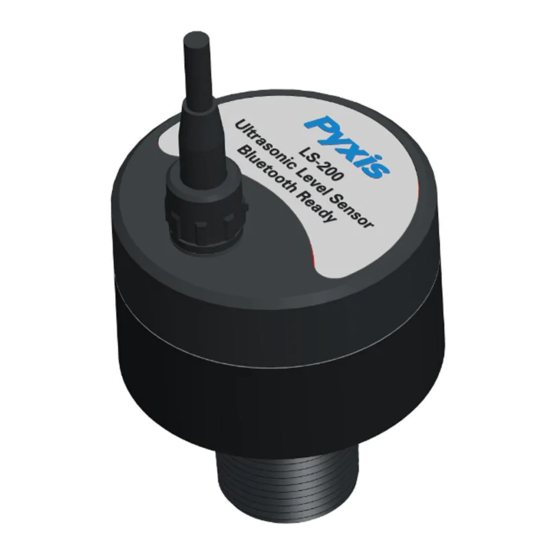
1 Introduction The Pyxis LS-200 is a general-purpose ultrasonic sensor. It provides continuous level measurement up to 86 inches (7.2 ft or 2.2 m) with a 4–20mA output, RS-485, and Bluetooth digital outputs. It can be configured via the uPyxis® App on your mobile phones or computers. The sensor is powered by a 24 VDC external power supply. -
Page 6: Standard Provided Accessories
• Waterproof Cable Adapter/Flying Leads (10 ft) P/N: 50774 • User Manual available online at https://pyxis-lab.com/product/ls-200-ultrasonic-level-sensor/ 3.2 Optional Accessories The following optional accessories can be ordered from Pyxis Customer Service (order@pyxis-lab.com) or Pyxis eStore at https://pyxis-lab.com/shop/. Figure 1. 4 Installation 4.1 Tank Top Installation and Precautions The sensor should be installed to a 1-inch bulkhead fitting on the top of the tank. -
Page 7: Wiring
22–26 VDC @ 65 mA. NOTE The negative 24V power terminal (power ground) and the negative 4–20mA ter- minal on the LS-200 are internally connected. Follow the wiring table below to connect the LS-200 to a controller: Table 2. Wire Color Designation... -
Page 8: Instrument Overview
NOTE The Bluetooth connected LED will illuminate within 30 seconds of powerup of the device. This feature is designed to minimize controller power draw during startup. Figure 4. Sensor connection and indicators LS-200 User Manual service@pyxis-lab.com | +1 (866) 203-8397... -
Page 9: Setup With Upyxis® Mobile App
1. Open uPyxis® Mobile App. 2. On uPyxis® Mobile App, pull down to refresh the list of available Pyxis devices. 3. If the connection is successful, the LS-200 and its Serial Number (SN) will be displayed (Figure 6). 4. Press on the LS-200 image. -
Page 10: Overview Screen
Figure 6. 6.3 Overview Screen When connected, the uPyxis® Mobile App will default to the OVERVIEW screen. The Overview screen displays the current liquid level and volume of liquid remaining. Figure 7. LS-200 User Manual service@pyxis-lab.com | +1 (866) 203-8397... -
Page 11: Reading Screen
• Tank Volume (rated volume capacity of the tank) • Installation Height (from the bottom of the tank to the bottom of the LS-200) • Max Level Height (from the bottom of the tank to the liquid surface when filled to the rated capacity) -
Page 12: Setup With Upyxis® Desktop App
Desktop application. Double click the uPyxis.Setup.exe file to install. Figure 11. uPyxis® desktop app installation Click Install to start the installation process. Follow the screen instructions to complete the USB driver and uPyxis® installation. LS-200 User Manual service@pyxis-lab.com | +1 (866) 203-8397... -
Page 13: Connecting To Upyxis® Desktop App
2. Launch uPyxis® Desktop App. 3. On uPyxis® Desktop App, click Device Connect via USB-Bluetooth (Figure 12). 4. If the connection is successful, the LS-200 and its Serial Number (SN) will be displayed in the left pane of the uPyxis® window. NOTE After the sensor and Bluetooth is powered up, it may take up to 10 seconds for the adapter to establish the wireless signal for communication. -
Page 14: Reading Screen
Figure 13. 7.4 Reading Screen The Reading screen displays the current liquid level and the liquid level over time. Figure 14. LS-200 User Manual service@pyxis-lab.com | +1 (866) 203-8397... -
Page 15: Setting Screen
• Tank Volume (rated volume capacity of the tank) • Installation Height (from the bottom of the tank to the bottom of the LS-200) • Max Level Height (from the bottom of the tank to the liquid surface when filled to the rated capacity) -
Page 16: Outputs 8.1 4-20Ma Output Setup
The sensor can be configured as a Modbus slave device via RS-485. In addition to the level, volume, and distance, many operational parameters, including warning and error messages, are available via a Modbus RTU connection. Contact Pyxis Lab Customer Service (service@pyxis-lab.com) for more information. 9 Sensor Maintenance and Precaution For best performance, keep the sensor ultrasonic surface clean using a soft cloth or towel. -
Page 17: Regulatory Approval
10 Regulatory Approval United States The LS-200 sensor has been tested and found to comply with the limits for a Class B digital device, pursuant to part 15 of the FCC Rules. These limits are designed to provide reasonable protection against harmful interference in a residential installation.
Need help?
Do you have a question about the LS-200 and is the answer not in the manual?
Questions and answers