
Related Manuals for Pyxis ST-565


Summary of Contents for Pyxis ST-565
- Page 1 ST-565 / ST-565T Inline HST or TTA Fluorometer Probe Instruction Manual Version 1.2 August 2018...
-
Page 2: Table Of Contents
Connecting to uPyxis Desktop App 6.5. Connecting to Device 6.6. Diagnosis Screen 6.7. Calibrating Device 6.8. Zero Calibration 6.9. Slope Calibration 6.10. 4-20 mA Span 7. Communicating Using Modbus RTU 8. Probe Cleaning and Maintenance 8.1. ST-565/T Inline Probe Cleaning Solution... -
Page 3: Introduction
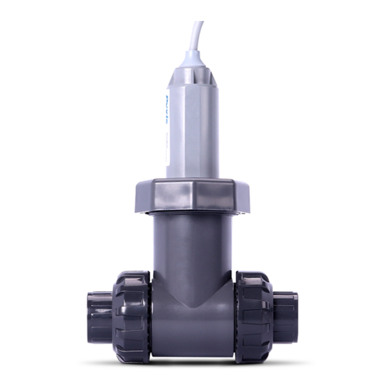
Triazole (HST) in cooling tower water. The ST565T is the same device configured to measure Tolytriazole (TTA). The ST-565 & 565T probes excite the sample water with a deep UV light and measures a narrow band near UV fluorescent emission. It can be connected to any controller that accepts an isolated or non-isolated 4-20mA input. -
Page 4: Optional Accessories
2 ppm TTA Calibration Standard Solution (Item Number: TTA-02) • 2ppm HST Calibration Standard Solution (Item Number: HST-02) 3. Specification Items Specification ST-565 (HST Only) 0-7.5 ppm, ±0.2 ppm precision ST-565T (TTA Only) 0-10ppm, ±0.2 ppm precision Power Supply 24 VDC, ~1W... - Page 5 4. Installation The ST-565/ST565T probe is shipped in a PVC tee. The tee has two ¾ inch NPT ports (sample in and out) and can be fluidically connected to a sample panel. The orientation of the flow with respect to the gravity of earth is not critical.
-
Page 6: Probe To Controller Installation
4.1. Probe to Controller Installation Follow the wiring table below to connect the ST-565/ST-565T probe to a controller. Note that the 24V power ground and the negative 4-20 mA terminal in the ST-565/ST-565T probe are internally connected. If a separate DC power supplier other than that from the controller is used, make sure that the output from the power supplier is within 22 to 26 VDC. -
Page 7: Probe Calibration With Upyxis Mobile App
Google Play 5.2. Connecting to uPyxis Mobile App Turn on Bluetooth on your mobile phone (Do not pair the phone Bluetooth to the ST-565). Open uPyxis Mobile App. uPxis App connects to the Probe and click on the ST-565 probe. -
Page 8: Diagnosis Screen
5.3. Diagnosis Screen From the Diagnosis screen. You can check the diagnosis condition, Export & Upload, and Upload Diagnosis Data. -
Page 9: Calibration Screen
5.4. Calibration Screen and Reading When connected, Mobile App will default to the Calibration screen. From the Calibration screen you can perform calibrations by pressing on Zero Calibration, Slope Calibration, 4-20 mA Span. Follow the screen instructions for each calibration step. -
Page 10: Device Info Screen
5.5. Device Info Screen From the Device Info screen. You can name the Device or Product. -
Page 11: Probe Calibration With Upyxis Desktop App
6. Probe Calibration with uPyxis Desktop App 6.1. Download uPyxis Desktop App Download uPyxis Desktop App from https://pyxis-lab.com/support-2/. -
Page 12: Unzip Upyxis Desktop App
6.2. UnZip uPyxis Desktop App Find your downloaded uPyxis Setup 1.3.8 file, Right Click on the file, Extract All, and then Extract. -
Page 13: Installing Upyxis Desktop App
6.3. Installing uPyxis Desktop App Once the uPyxis Desktop App has been extracted. Find the extracted uPyxis Setup file and left click, click on Run, and then click Install. After install has been clicked the Setup Progress will continue. Follow the step during installation process. -
Page 14: Connecting To Upyxis Desktop App
6.4. Connecting to uPyxis Desktop App Open uPyxis Desktop App on your desktop. When the desktop app opens, to find your device, click on Device, then Connect via WiFi. -
Page 15: Connecting To Device
6.5. Connecting to Device When connected via WiFi, in the Discovered Devices box there will be the device product name (If no device product name in the Discovered Devices box, click Refresh). If device product name shows in the box, then click on Connect to Device. -
Page 16: Diagnosis Screen
6.6. Diagnosis Screen After the device has been calibrated and installation has been completed. To check diagnosis, click on Diagnosis. When in the Diagnosis screen you can view the Diagnosis Condition of the device. -
Page 17: Calibrating Device
6.7. Calibrating Device To calibrate the device, click on Calibration. On the Calibration screen there are three calibration tabs, Zero Calibration, Slope Calibration, and 4-20 mA Span. The screen does also display the reading of the device. The reading refreshed rate is every 4 seconds. 6.8. -
Page 18: Slope Calibration
6.9. Slope Calibration To perform Slope Calibration, click on Slope Calibration. Then follow the instruction on how to calibrate, then click Slope Calibration. 6.10. 4-20 mA Span To perform 4-20 mA Span, click on 4-20 mA Span. Then follow the instruction on how to calibrate, then click 4-20 mA Span. -
Page 19: Communicating Using Modbus Rtu
7. Communicating using Modbus RTU The ST-565 / ST-565T probe is a Modbus slave device. In addition to the ppm TTA/HST value, a range of operational parameters including warning and error message are available via Modbus RTU connection. Contact Pyxis Lab Customer Service (service@pyxis-lab.com) for more information.
Need help?
Do you have a question about the ST-565 and is the answer not in the manual?
Questions and answers