Advertisement
Quick Links
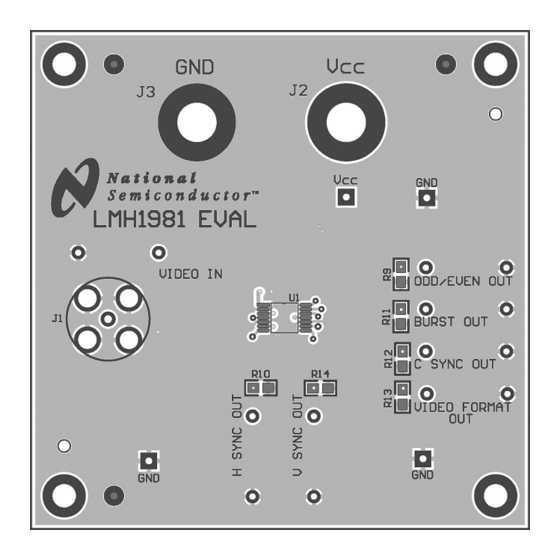
LMH1981 Evaluation Board
Instruction Manual
General Description
The LMH1981 Evaluation Board can be used to evaluate the
LMH1981 Multi-Format Sync Separator and as a reference
for designing the PCB layout. Refer to the LMH1981
datasheet for more information on PCB layout considerations.
Power Supply
The board should be powered with a clean supply voltage of
3.3V to 5.0V using the banana jacks V
The supply should be well-regulated within ±5% variation of
the voltage range and should not be shared directly with other
digital circuitry.
Video Input
A high-quality DC-coupled video source should be connected
to the video input BNC (J1), which is terminated on-board via
a 75Ω load resistor. For AC-coupled video sources, it may be
necessary to reduce the value of the input coupling capacitor
(C4) as described in the datasheet; otherwise, sync loss may
occur during significant changes in video average picture lev-
Board Schematic
© 2009 National Semiconductor Corporation
National Semiconductor
Application Note 1599
February 11, 2009
el (e.g. random white-to-black field transitions). It is recom-
mended to drive the LMH1981 input by a professional-grade
DC-coupled video reference.
Because the input can accept either SD or HD video inputs,
the PCB footprints for the chroma filter components were not
populated. For SD composite video inputs, it may be neces-
sary to use a RC low-pass filter to attenuate the chroma
component so it does not extend below the 50% sync level
and also to improve overall signal-to-noise ratio. The RC filter
cutoff frequency is typically set between 0.5 MHz and 2 MHz,
(J2) and GND (J3).
CC
which corresponds to chroma attenuation between 17 dB and
6 dB for a 3.58 MHz subcarrier (NTSC). For HD video inputs,
it is suggested to bypass any composite video filtering, as it
may reduce the bandwidth of the HD tri-level sync signal and
thus increase timing jitter on the HSync output.
Test Points
Test points are provided to probe the input and output signals
using oscilloscope probes with high input impedance and low
capacitance.
300126
30012601
www.national.com
Advertisement

Subscribe to Our Youtube Channel
Related Manuals for National Semiconductor LMH1981


Summary of Contents for National Semiconductor LMH1981
-
Page 1: General Description
(e.g. random white-to-black field transitions). It is recom- General Description mended to drive the LMH1981 input by a professional-grade The LMH1981 Evaluation Board can be used to evaluate the DC-coupled video reference. LMH1981 Multi-Format Sync Separator and as a reference Because the input can accept either SD or HD video inputs, for designing the PCB layout. -
Page 2: Board Layout
Board Layout 30012604 Top Side 30012605 Bottom Side www.national.com... -
Page 3: Bill Of Material
Bill of Material Item Mfr. Part Number Part Description Remark Designator 551012810-002A LMH1981MTEVAL LMH1981MT TSSOP-14 Cer Cap 0.1 µF 25V X7R 0805 C1,C2 Cer Cap 1 µF 10V X5R 0805 Tant Cap 10 µF 10V TANT-A (3216) Res 10 kΩ 0.125W 1% 0805 Res 75Ω... - Page 4 Notes For more National Semiconductor product information and proven design tools, visit the following Web sites at: Products Design Support Amplifiers www.national.com/amplifiers WEBENCH® Tools www.national.com/webench Audio www.national.com/audio App Notes www.national.com/appnotes Clock and Timing www.national.com/timing Reference Designs www.national.com/refdesigns Data Converters www.national.com/adc Samples www.national.com/samples...
Need help?
Do you have a question about the LMH1981 and is the answer not in the manual?
Questions and answers