Table of Contents
Advertisement
Quick Links
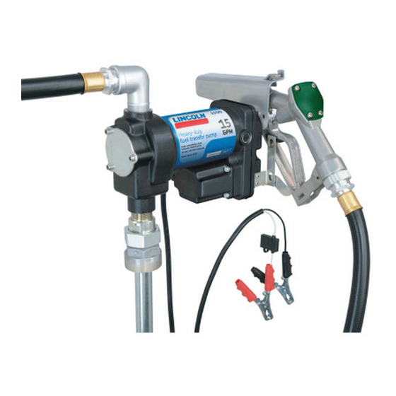
Fuel transfer pump
Model 1550, 12 V DC 15 gal./min.
July 2014
Date of issue
Form number
404605A
Section
B5
Page
51A
D A N G E R
Read manual prior to installation or use
of this product. Keep manual nearby for
future reference. Failure to follow
instructions and safety precautions may
result in death or serious injury.
Installation and maintenance guide
Advertisement
Table of Contents

Related Manuals for Lincoln 1550


Summary of Contents for Lincoln 1550
- Page 1 Installation and maintenance guide Fuel transfer pump Model 1550, 12 V DC 15 gal./min. July 2014 Date of issue D A N G E R Form number 404605A Read manual prior to installation or use Section of this product. Keep manual nearby for Page future reference.
-
Page 2: Power Source Requirements
Power source Optional accessories requirements Spin On 30um Filter 25100 The Lincoln model 1550 fuel transfer pump Filter Head, Spin-On 25113 features a rotary vane pump design utilizing A 12 V DC power supply is required to Fuel Filter Kit 25114 a 12 V DC motor. -
Page 3: Work Area Safety
Personal safety The pump must be properly grounded. W A R N I N G Always use the supplied fuse holder and 40 A fuse. Stay alert, watch what you are doing, and Read all safety warnings and all instruc- Only use the power cord that was sup- use common sense when operating the tions. - Page 4 Product use and care Notice Notice W A R N I N G Always disconnect the tool Do not use pump to transfer Do not use pump to transfer gasoline. from its power source before making water. Damage to pump will occur. Risk of explosion.
-
Page 5: Assembly And Installation
Service Assembly and 4 Tighten the 1 in. (25,4 mm) NPT internal installation thread of the adapter (27) into the pump inlet (1 in. NPT). Remove all components from packaging and 5 Measure the depth of the tank from top ensure all components are present. - Page 6 Fig. 8 Notice Notice If tank is less than 12.5 in. Over torque of bolts († step 9) (3,8 mm) deep, cut the rigid extension can result in damage to casting. tube to desired length allowing at least 0.5 in. (0,500 mm) between tube and tank bottom when assembled.
-
Page 7: Electrical Wiring
Electrical wiring Hard wire to vehicle’s battery 3 Route the new wire to a proper grounding location on a steel or metal chassis component. 4 Install a ring terminal on end of wire and fasten the terminal with a screw. W A R N I N G C A U T I O N Notice... -
Page 8: Operation
Operation Notice C A U T I O N Avoid routing wires near areas of 1 Remove the fuel control nozzle from the high temperature, sharp edges, or any Do not rig control nozzle handle to stay nozzle hanger. environment that may cause damage to open. -
Page 9: Brush Replacement
Service Switch repair 11 Adjusting the toggle switch nuts changes 1 Remove the (6) M5-0.8mm screws from how soon the toggle switch is engaged. Rotor and vane replacement the casting. Slight twisting of the shaft forks may be 2 Loosen and remove the M8 lock nut necessary to get proper alignment. - Page 10 Troubleshooting Condition Possible cause Remedy Motor not operating. Blown fuse. Locate fuse holder and replace fuse. Power supply voltage is too low. Check battery electrical connections Recharge battery Jammed rotor. Remove pump access plate and remove any debris stuck between vane, rotor, and/or inlet/ outlet ports.
- Page 11 Fig. IPB1 Exploded view Install a 30 micron filter (not provided) prior to pump outlet hose (30).
- Page 12 Fig. IPB2 Exploded view...
- Page 13 Fig. IPB3 Exploded view...
- Page 14 Service parts Item no. Description Qty. Part no. Item no. Description Qty. Part no. Screw, M6-1 mm pitch x 10 mm long Casting, junction box None Vane access plate 278913 Screw, M5-0.8 pitch x 10 mm long None O-ring, 2.6 mm WD x 56.8 mm ID Vane Clamps, battery (positive &...
-
Page 15: Lincoln Industrial Standard Warranty
(international number 01-314-679-4200) required. ranty on this equipment is limited to repair or you may also use our website In no event shall Lincoln be liable for inci- with Lincoln paying for parts only. www.lincolnindustrial.com dental or consequential damages. Lincoln’s... - Page 16 ® SKF is a registered trademark of the SKF Group. ® Lincoln is a registered trademark of Lincoln Industrial Corp. © SKF Group 2014 The contents of this publication are the copyright of the publisher and may not be reproduced (even extracts) unless prior written permis- sion is granted.
Need help?
Do you have a question about the 1550 and is the answer not in the manual?
Questions and answers