Table of Contents
Advertisement
INSTALLER: P LEASE FAMILIARIZE YOURSELF WITH THIS MANUAL BEFORE PROCEEDING WITH THE
INSTALLATION. LEAVE THIS MANUAL WITH THE APPLIANCE FOR FUTURE REFERENCE.
CONSUMER: RETAIN THIS MANUAL FOR FUTURE REFERENCE.
THRU-THE-WALL PACKAGED UNIT
CONFORMS TO ANSI/UL STD. 1995, ANSI STD. Z21.47
CERTIFIED TO CAN/CSA STD. C22.2 NO. 236,
CAN/CSA STD. 2.3 AND CAN/CGA STD. 2.17
9700539
WARNING
!
ELECTRICAL SHOCK, FIRE OR EXPLOSION
HAZARD
FAILURE TO FOLLOW SAFETY WARNINGS
AND INSTRUCTIONS EXACTLY COULD
RESULT IN SERIOUS INJURY, DEATH OR
PROPERTY DAMAGE.
IMPROPER INSTALLATION, ADJUSTMENT,
ALTERATION, SERVICE, OR MAINTENANCE
CAN CAUSE INJURY OR PROPERTY
DAMAGE. REFER TO THIS MANUAL.
INSTALLATION AND SERVICE MUST BE
PERFORMED BY A QUALIFIED INSTALLER,
SERVICE AGENCY, OR THE GAS SUPPLIER.
UNIT CONTAINS R-410A REFRIGERANT AND
POE COMPRESSOR OIL.
USE ONLY R-410A REFRIGERANT AND
APPROVED POE COMPRESSOR OIL.
PROPER SERVICE EQUIPMENT IS
REQUIRED. USE ONLY R-410A APPROVED
SERVICE EQUIPMENT.
FOR YOUR SAFETY, DO NOT STORE OR
USE GASOLINE OR OTHER FLAMMABLE
VAPORS AND LIQUIDS IN THE VICINITY OF
THIS OR ANY OTHER APPLIANCE. SUCH
ACTIONS COULD RESULT IN PROPERTY
DAMAGE, PERSONAL INJURY, OR DEATH.
CAUTION
!
INSTALLATION SHALL BE MADE IN
ACCORDANCE WITH THE REQUIREMENTS OF
THE LOCAL AUTHORITIES HAVING
JURISDICTION, AND WITH THE NATIONAL
FUEL GAS CODE, ANSI Z223.1 (LATEST
EDITION) AND THE NATIONAL ELECTRICAL
CODE IN THE UNITED STATES OR
CAN/CGA-B149.1 & .2 AND THE CANADIAN
ELECTRICAL CODE CSA C22.1 PART 1
(LATEST EDITION) IN CANADA.
ANY ALTERATION OF INTERNAL WIRING WILL
VOID CERTIFICATION AND WARRANTIES.
INSTALLATION AND OPERATING
HIGH EFFICIENCY CONDENSING
GAS HEAT & ELECTRIC COOLING
!
THE HIGHEST EFFICIENCY THRU-THE-WALL
SELF CONTAINED HEATING & COOLING UNIT
• Installation and service must be performed by a qualifi ed
installer, service agency or the gas supplier.
• Before servicing, disconnect all electrical power to unit.
• When servicing controls, label all wires prior to disconnecting.
Reconnect wires correctly.
• Verify proper operation after servicing.
• Do not store or use gasoline or other fl ammable vapors and
liquids in the vicinity of this or any other appliance.
• After installing the unit, show user locations of main electrical
disconnect switch to Condopack and how the unit can be
de-energized using switch.
!
WHAT TO DO IF YOU SMELL GAS:
■
Do not try to light any appliance.
■
Do not touch any electrical switch; do not use any phone in your unit.
■
Leave the unit immediately.
■
Immediately call your gas supplier from a neighbor's phone.
Follow the gas supplier's instructions.
■
If you cannot reach your gas supplier, call the fi re department.
MANUFACTURER RESERVES THE RIGHT TO DISCONTINUE, OR CHANGE AT ANY TIME,
SPECIFICATIONS OR DESIGNS WITHOUT NOTICE AND WITHOUT INCURRING OBLIGATIONS.
Wolf Steel Ltd�, 24 Napoleon Rd�, Barrie, ON, L4M 0G8 Canada /
103 Miller Drive, Crittenden, Kentucky, USA, 41030
Phone (866) 820-8686 • Fax (705) 725-1150 • www.napoleonheatingandcooling.com
INSTRUCTIONS
IMPORTANT
!
• Email: hvac@napoleonproducts.com •
IOM
!
W415-1307 / B / 03.31.2017
Advertisement
Table of Contents
Troubleshooting

Summary of Contents for Wolf Steel Condo Pack
- Page 1 CAN/CGA-B149.1 & .2 AND THE CANADIAN MANUFACTURER RESERVES THE RIGHT TO DISCONTINUE, OR CHANGE AT ANY TIME, SPECIFICATIONS OR DESIGNS WITHOUT NOTICE AND WITHOUT INCURRING OBLIGATIONS. ELECTRICAL CODE CSA C22.1 PART 1 Wolf Steel Ltd�, 24 Napoleon Rd�, Barrie, ON, L4M 0G8 Canada / (LATEST EDITION) IN CANADA. 103 Miller Drive, Crittenden, Kentucky, USA, 41030 ANY ALTERATION OF INTERNAL WIRING WILL Phone (866) 820-8686 • Fax (705) 725-1150 • www.napoleonheatingandcooling.com...
-
Page 2: Table Of Contents
TABLE OF CONTENTS 1. MODEL NOMENCLATURE ......................... 3 2. OVERVIEW ..............................3 3. SAFETY ............................... 4 3.1 SAFETY SYMBOLS AND WARNINGS ��������������������������������������������������������������������������������������������������������������������������� 4 ���������������������������������������������������������������������������������������������������������������7 3.2 SAFETY RULES 3.3 CODES ��������������������������������������������������������������������������������������������������������������������������������������������������������������������������� 8 4. INSTALLATION ............................9 4.1 UNIT DIMENSIONS ��������������������������������������������������������������������������������������������������������������������������������������������������������� 10 4.2 UNIT LOCATION AND CLEARANCES ������������������������������������������������������������������������������������������������������������������������� 11 4.3 PACKAGED UNIT PREPARATION �������������������������������������������������������������������������������������������������������������������������... -
Page 3: Model Nomenclature
E l e c t r i c H eat H yd ro n i c H e at PSC040B018A Heat designation Heat designation - Condo Pack 000 - Duct Only 000 - Duct Only - Single Packaged Vertical 005 - 5.0 kW... -
Page 4: Safety
3. SAFETY Only trained service technicians familiar with standard service instructions and training materials should attempt installation, service, and repair of these units. Improper installation, adjustment, alteration, service, maintenance, or use can cause explosion, fire, electrical shock, or other conditions which may cause death, personal injury, or property damage. For information and assistance, consult a qualified installer, service agency, your distributor or branch. Follow all safety codes. Wear safety glasses, protective clothing, and work gloves. Have fire extinguisher available. Read instructions thoroughly and follow all warnings or cautions included in literature and attached to the unit. Consult federal, provincial, state, and local codes for special requirements. SAFETY SYMBOLS AND WARNINGS Understand and pay particular attention to the words DANGER, WARNING, and CAUTION and the following defi ned symbols are used throughout this manual to notify the reader of potential hazards of varying risk levels. DANGER INDICATES AN IMMINENTLY HAZARDOUS SITUATION WHICH, IF NOT AVOIDED, WILL RESULT IN DEATH OR SERIOUS INJURY. WARNING INDICATES A POTENTIALLY HAZARDOUS SITUATION WHICH, IF NOT AVOIDED, COULD RESULT IN DEATH OR SERIOUS INJURY. - Page 5 WARNING IF THE INFORMATION IN THESE INSTRUCTIONS IS NOT FOLLOWED EXACTLY, A FIRE OR EXPLOSION MAY RESULT, CAUSING PROPERTY DAMAGE, PERSONAL INJURY OR DEATH. FOR YOUR SAFETY DO NOT STORE OR USE GASOLINE OR OTHER FLAMMABLE VAPORS AND LIQUIDS, OR OTHER COMBUSTIBLE MATERIALS IN THE VICINITY OF THIS OR ANY OTHER APPLIANCE.
- Page 6 WARNING THIS INFORMATION IS INTENDED FOR USE BY QUALIFIED HVAC TECHNICIANS. ANY ATTEMPT TO REPAIR A CENTRAL AIR CONDITIONING PRODUCT MAY RESULT IN PERSONAL INJURY AND/OR PROPERTY DAMAGE. THE MANUFACTURER OR SELLER CANNOT BE RESPONSIBLE FOR THE INTERPRETATION OF THIS INFORMATION, NOR CAN IT ASSUME ANY LIABILITY IN CONNECTION WITH ITS USE.
-
Page 7: Safety Rules
SAFETY RULES 1� Use this unit only with type of gas approved for the furnace module. Refer to the unit rating plate. 2. Store this unit only in dry indoor locations (protected from weather). 3� DO NOT install this unit outdoors or in a mobile home, trailer or recreational vehicle. This appliance is not designed/certified for these installations. 4� DO NOT install unit in a corrosive or contaminated atmosphere. 5. For lighting and shutting down the furnace refer to “Furnace Start Up and Furnace Shut Down”, section 5 of this manual. 6� Install this unit only in dry indoor locations (protected from weather). 7. Provide adequate combustion and ventilation air to the unit space as specified in section 4.9 “Venting and Combustion Piping”. 8� Combustion products must be discharged outdoors using factory installed vent system only, as specified in section 4.9 “Venting and Combustion Piping”� 9. Never test for gas leaks with an open flame. Use a commercially available soap solution made specifically for the detection of leaks to check all connections as specified in “Gas Supply and Piping” section of this manual. -
Page 8: Codes
CODES 1. This unit must be installed: a� In accordance with all local codes, by-laws and regulations by those authorities having jurisdiction. b. I n Canada, this furnace must be installed in accordance with the current CAN/CGA-B149.1 and B149.2 Natural Gas and Propane Code. c� In the United States, this furnace must be installed in accordance with the current ANSI Z223.1 (NFPA 54) National Fuel Gas Code. 2. Electrical connections must be made in accordance with: a� Any applicable local codes, by-laws and regulations. b. Canada: current edition of CAN/CSA C22.1 and C22.2, Canadian Electrical Code (Part 1 and 2). c� United States: current edition of ANSI/NFPA 70, National Electrical Code. 3. Codes and additional information may be obtained from: Canadian Standards Association National Fire Protection Association American Gas Association... -
Page 9: Installation
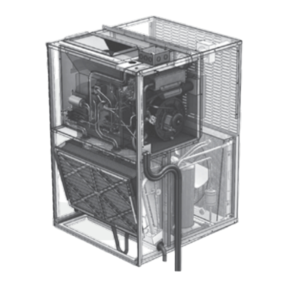
4. INSTALLATION WALL SLEEVE The unit is shipped in one CHASSIS package, completely assembled CABINET and wired. The air conditioning PRIMARY HEAT and furnace condensate drains EXCHANGER are shipped separately with the SUPPLY OUTLET ELECTRICAL unit for field install. If any damage is found, proper COMBUSTION notation should be made on the DISCHARGE CONNECTION TERMINAL FURNACE carrier’s freight bill. Damage MODULE claims should be filed with the THERMOSTAT ACCESS WIRING carrier as quickly as possible. SLOT FLAME PANEL INSPECTION CONTROL WINDOW BOARD Check the rating plate (at the INSPECTION WINDOW FILTER front of the access panel) to... -
Page 10: Unit Dimensions
UNIT DIMENSIONS 16" Combustion discharge 16 " terminal 8 " 2 " 4 " 4 " 8 " 8" SUPPLY OUTLET ELECTRICAL CONNECTION GAS CONNECTION 28" *When flexible connectors are used, the maximum length 2 " 29" shall not exceed 36”. Flame inspection window... -
Page 11: Unit Location And Clearances
UNIT LOCATION AND CLEARANCES NOTE OUTSIDE Sleeve Flange ALTHOUGH IT IS NOT POSSIBLE TO DETAIL ALL OF CONSTRUCTION PARAMETERS THAT COULD BE ENCOUNTERED, THE FOLLOWING GUIDELINES AND PRECAUTIONS ARE RECOMMENDED: Drain holes • MASONRY WALLS MUST HAVE A LINTEL TO SUPPORT THE WALL. • DURING THE WALL SLEEVE ASSEMBLY PAY ATTENTION THAT THE SIDE PANEL FLANGES AND THE BASE PANEL DRAIN HOLES ARE ON THE SAME SIDE OF WALL SLEEVE, SEE FIG 4.2. - Page 12 4.2.1 Venting Guidelines This appliance should be installed in a location such that the vent outlet is located in the following manner: In Canada: In addition to the general guidelines, in Canada, the vent exhaust shall not terminate: • Directly above a paved sidewalk or paved driveway which is located between two single-family dwellings and serves both dwellings; • Less than 7 feet (2.1m) above a paved sidewalk or paved driveway located on public property; • Within 6 feet (1.8m) of a mechanical air supply inlet to any building; • Above a meter/regulator assembly within 3 feet (.91m) horizontally of the center line of the regulator; • Within 3 feet (.91m) of any service regulator vent outlet; • Less than 12” (305mm) above grade level or anticipated snow level; • Within 12” (305mm) of any door, window that can be opened, or non-mechanical air supply inlet to any building; • Within 12” (305mm) of the combustion air inlet of any other appliance; • Recommended practice (where practicable) is to maintain the same vertical clearance between the vent and the overhang as the horizontally distance the overhang protrudes from the building. • Unless governing bodies having local jurisdiction specify a minimum clearance larger, the minimum clearance between a vent terminal and a overhanging structure shall be 40 inches (1m). In USA: H14.2A_AC In addition to the general guidelines, in the United States, the vent exhaust shall be installed in accordance with the following: • The clearance from the bottom of the terminal to grade shall be 12” (305mm). • The vent shall not terminate over public walkways or over an area where condensate or vapor could create a nuisance or hazard.
- Page 13 OBJECTS. SOME DISCOLORATION IS TO BE EXPECTED. Check local codes for distance between vent terminal and a inside corner formed by two exterior walls. If not specifi ed by local code, minimum distance between vent terminal and an inside corner formed by two exterior walls is 6 inches (0.15m). Recommended vertical clearance of a vent terminal and overhanging structure should be maximized to prevent condensate products from depositing and freezing on overhang. This practice helps prevent degradation of building materials. Recommended practice (where practicable) is to maintain the same vertical clearance between the vent and the overhang as the horizontal distance the overhang protrudes from the building. Unless governing bodies having local jurisdiction specify a minimum clearance larger, the minimum clearance between a vent terminal and a overhanging structure shall be 40 inches (1m). Any adjacent painted surfaces should be in good condition; no cracks, peeling paint, etc. If wooden surfaces that may be periodically exposed to fl ue gases are present, consider treating with a sealer. H15.5_CP WARNING THIS FURNACE IS CERTIFIED FOR INSTALLATION ON COMBUSTIBLE FLOORS. THIS SHALL BE INTERPRETED AS A WOOD FLOOR ONLY. THE FURNACE MUST NOT BE INSTALLED DIRECTLY ON CARPETING, OR OTHER COMBUSTIBLE MATERIAL EXCEPT WOOD.
- Page 14 FIG. 4.2.1 - DIRECT VENT TERMINAL CLEARANCES W415-1307 / B / 03.31.2017...
- Page 15 The minimum clearances required for installation and accessibility are shown below. These clearances should be followed unless otherwise approved by the manufacturer. FIG. 4.2.2. W415-1307 / B / 03.31.2017...
-
Page 16: Packaged Unit Preparation
PACKAGED UNIT PREPARATION NOTE • THIS UNIT MUST BE INSTALLED IN ACCORDANCE WITH ALL APPLICABLE CODES. • THIS UNIT IS APPROVED FOR THRU-THE-WALL INSTALLATION ONLY. • THESE INSTALLATION AND MAINTENANCE INSTRUCTIONS SHOULD BE LEFT WITH THE UNIT FOR FUTURE REFERENCE. Prior to installing the unit in the wall opening: 1� Remove the brackets connecting the unit to the skid. 2� Remove the cooling module. IMPORTANT 1. The unit must be installed a minimum of 8” above finished floor. a. If unit is installed in a storage garage, all ignition sources (electric contactors and motors included) must be positioned at a minimum of 18” (457mm) above the floor, and it must be protected from physical damage by vehicles, consistent with CAN/ CSA-B149. -
Page 17: Wall Sleeve Assembly
WALL SLEEVE ASSEMBLY WARNING THESE INSTRUCTIONS ARE INTENDED AS AN AID TO QUALIFIED SERVICE PERSONNEL FOR PROPER INSTALLATION, ADJUSTMENT AND OPERATION OF THE UNIT. READ THESE INSTRUCTIONS THOROUGHLY BEFORE ATTEMPTING INSTALLATION OR OPERATION. IMPROPER INSTALLATION, ADJUSTMENT, SERVICE, OR MAINTENANCE CAN CAUSE PROPERTY DAMAGE, PERSONAL INJURY, OR DEATH. CONSULT A QUALIFIED INSTALLER OR SERVICE AGENCY FOR INFORMATION AND ASSISTANCE. - Page 18 Place Base part (2) on the fl oor and attach Right Side Panel (3): a� Position Base Panel (2) to seat behind fl anges on the Side Panel (3)� b. Bring together panel clips and openings (FIG. 1). Press down Press down Press down Press down fi rmly to lock base panel into place (FIG. 2). Attach Left Side Panel (4) to Base (2). Repeat procedure from step 2 (FIG. 2). W415-1307 / B / 03.31.2017...
- Page 19 Check for parallel position of Left and Right Side Panels (3) and (4). Secure connection with Base Panel (2), see (FIG. 4). Attach Top Panel (1) to Left and Right Side Panels (3) and (4). Align connection openings and secure the assembly by pushing the clips in place (FIG. 5). 10” Attach Squaring Braces (10) to the inner sides of both, Top Panel and the Side Panels, by inserting the screws (7) from inside. To attach the Squaring Brace (10) to the Side Panels (3) and (4) use the 1/8” holes located 10” down from the top and 4 -5/16” from the outside fl ange (FIG. 6. and FIG. 7). 10” 10” 10” 10” 10” 10” W415-1307 / B / 03.31.2017...
- Page 20 NOTE: The following support bracket locations are for installations where the wall sleeve is installed from the OUTSIDE of the building. For installations where the wall sleeve is installed from the INSIDE of the building, the Side Support Brackets (5) need to be mounted on INTERIOR wall, so they will need to be relocated on the wall sleeve (new screw 10”...
- Page 21 Wall Sleeve Dimensions FOUR DIFFERENT WALL SLEEVE MODELS ARE DEPICTED BELOW: • CWSMUA • CWSMUA15 • CWSMUA17 • CWSMUA19 Position B Position A NOTE: TO IMPROVE RIGIDITY AND REDUCTION IN VIBRATION WALL MOUNTING BRACKETS CAN BE USED TO AFFIX WALL SLEEVE TO BUILDING SUB STRUCTURE FROM INSIDE OR OUTSIDE OF THE BUILDING.
- Page 22 4.4.1 Wall Sleeve Installation WARNING INSTALLATION CREW MUST ADHERE TO ALL LOCAL/NATIONAL SAFE WORK PRACTICES INCLUDING EMPLOYING APPROPRIATE FALL ARREST EQUIPMENT To install Wall Sleeve into wall opening: Wall sleeve can be installed from inside or outside the building (FIG. 12). The side and top brackets’ position need to be adjusted to suit the method and building material. 1� With drain holes facing outside, position the sleeve towards the wall until the support brackets are set on wall edge. Leave ¼ “ space in between the wall and sleeve for caulking. 2� Ensure parallel position between Wall Sleeve and wall FROM INSIDE: opening. Wall Sleeve must be square for the CondoPack to Push the sleeve slide into it.
-
Page 23: Unit Support
UNIT SUPPORT The wall sleeve is not intended as the sole support for DO NOT OPERATE THE FURNACE FOR PROLONGED CAUTION the unit. Therefore, additional support must be provided PERIODS OF TIME WITHOUT AN AIR FILTER. A ALWAYS by a rigid structure that bears the weight of the unit and WEAR SAFETY GLASSES WHEN WORKING WITH provides an interface for “return air” ducting. TOOLS! OVER-TIGHTENING THE SCREWS MAY STRIP • First, the supporting platform must be built, see THE RETAINING HOLES. READ ALL OF THE ASSEMBLY (FIG. 14). It can be constructed of plywood and INSTRUCTIONS STEPS BEFORE PROCEEDING. -
Page 24: Packaged Unit Installation
PACKAGED UNIT INSTALLATION Procedure 1� Verify that isolation grommets are installed in the five holes on the top mounting bracket. 2� Bring the Condo Pack as close as possible to wall opening (FIG. 4�6�A). Carefully slide the unit into the Wall Sleeve (refer to section 4.4. “Wall Sleeve Assembly” and Installation Instructions) so the front of the unit is in contact with the front flanges of the Wall Sleeve� For ease of installation (OPTIONAL): a� Install cabinet into the Wall Sleeve without cooling unit. b. Slide cooling unit in, after cabinet is in place (FIG. 4�6�B) FIG. 4.6.A c� Furnace module also can be removed separately (FIG. 4�6�C)� Refer to section “4.16.4.2 Furnace Module Removal”� Air Conditioning module removal. Air Conditioning module can AC Module be removed for easier cabinet installation. Refer to section “4.16.4.1 Air Conditioner Module Removal”. -
Page 25: Ductwork
DUCTWORK 4.7.1 Supply Air Ducting IMPORTANT BOTH SUPPLY AND RETURN AIR MUST BE DUCTED TO THE APPLIANCE FROM ROOMS SEPARATE TO THE CLOSET ENCLOSURE HOUSING THE APPLIANCE. SUPPLY AIR DUCT (PLENUM) CONNECTION MUST BE AT LEAST THE SAME SIZE AS THE UNIT SUPPLY AIR OPENING. - Page 26 4.7.2 Return Air Ducting Provide the support inside the building in the area of the return air opening. The support should be high enough to allow for return air to the unit as per requirements. If required, install a resilient material between the support and the base of the unit to reduce the possible transmission of sound and vibration. Unit Flashing 7” Unit Opening To seal the unit to return air duct (below the support structure), perform following procedure steps: 24” 1� Cut a hole in the return air duct (24”x7”). 2� Align the unit opening with a return air 24”x7” Return Air duct cut out� Duct Opening 3� Insert steel sheet extension part A through the opening. Return Air Duct 4� Align the upper edges, adjusting the height. 5. Mount to the condo pack using four self- tapping screws provided. 6�...
-
Page 27: Condensate Drain Connection
CONDENSATE DRAIN CONNECTION The furnace and air conditioning condensate drain connections are included, but not installed. Both drain connections are already pre-fabricated with integral P traps. To connect condensate drains to the existing drainage systems, refer to illustrated installation steps 1-17: 5/8” ID 1/2” ID A - Furnace Hoses: A1 = 1/2” ID A2 = 5/8” ID B - AC Hose: C - Hose Clamp 1X C - Hose Clamp 2X B - AC Hose = 5/8” B = 5/8”... - Page 28 FAILURE TO FOLLOW EITHER OF THESE CONDITIONS DURING UNIT OPERATION COULD CAUSE EXHAUST PRODUCTS TO ENTER THE LIVING SPACE WHICH MAY RESULT IN PROPERTY DAMAGE, PERSONAL INJURY OR DEATH. Add water into In order for air conditioner drain B opening. to operate, this trap has to be filled with water as shown.
-
Page 29: Venting And Combustion Piping
VENTING AND COMBUSTION PIPING The venting system is an integral part of the appliance and is designed for proper operation under all weather conditions and for winds up to 32 miles per hour. The venting system must not be modified or added on to. The vent outlet must not be altered or extended. The unit contains an exhaust blower which draws the combustion products out of the heat exchanger together with dilution air and forces the mixture from the unit to the outside. No special provisions are required for supplying air for combustion, nor is a chimney required. 4.10 GAS SUPPLY AND PIPING In Canada, the gas piping should be installed in accordance with CAN/CSA-B149.1 and B149.2, and in accordance with any local codes. In the United States, the gas piping should be installed in accordance with (NFGC) NFPA 54 / ANSI Z223.1 and any local codes. If local codes allow the use of a flexible gas appliance connector, always use a new listed connector. Do not use a connector which has previously serviced another gas appliance. For a lever-type valve use only a shut-off gas valve approved by CAN/CSA B149. 4.11 GAS CONNECTIONS IMPORTANT ALWAYS USE A BACKSTOP WRENCH TO PREVENT TWISTING OF THE GAS VALVE. ANY STRAINS ON THE GAS VALVE CAN AFFECT POSITIONING OF THE ORIFICES RELATIVE TO THE BURNERS. -
Page 30: Gas Inlet Pressure
4.12 GAS INLET PRESSURE The natural gas inlet supply pressure should be 5” to 7” wc. (7” wc recommended). The LP gas inlet supply pressure should be 11” to 13” wc. (12” wc recommended). These pressures must be maintained while all other gas fired appliances are operating at maximum conditions. IMPORTANT DO NOT EXCEED 13” WC INLET PRESSURE FOR LP GAS AND 10.5” WC FOR NATURAL GAS. The gas valve has an adjustable internal regulator for controlling burner manifold pressure. Burner manifold pressure is listed on the furnace rating plate. WARNING THE 30, 40 AND 50K BTU FURNACES ARE FACTORY EQUIPPED TO BURN NATURAL GAS ONLY. CONVERSION TO LP GAS REQUIRES A NATURAL GAS TO LP CONVERSION KIT (W370-0040) EXCEPT FOR 15K BTU (CCGM015A) UNITS. -
Page 31: Leak Testing
4.13 LEAK TESTING All new gas piping installations should be pressure tested as specifi ed by CAN/CSA-B149.1 & 2, or NFPA 54 ANSI Z223.1 or ANSI/NFPA 58, “Standard for the Storage and Handling of Liquefi ed Petroleum Gases.” Gas piping that has not been pressure tested, from the manual shut-off valve to the furnace gas valve for example, should be leak tested using an electronic combustible gas detector, a commercially prepared leak detector, or other locally approved method. H17.4 4.14 PURGING GAS LINES Both, the unit and its manual gas shut-off valve must be disconnected from the gas supply piping system during any pressure testing of that system, if test pressure exceeds 1/2 psi (3.5 kPa). WARNING FIRE OR EXPLOSION HAZARD! NEVER TEST FOR GAS LEAKS WITH AN OPEN FLAME. NEVER USE A MATCH, TAPER, CIGARETTE LIGHTER, FLAME OR ANY OTHER IGNITION SOURCE TO CHECK FOR LEAKS IN A GAS LINE. - Page 32 4� Measure furnace gas inlet pressure with burners fi ring. Inlet pressure must be within the range specifi ed on the furnace rating plate. 5-7” w.c. (Natural Gas) or 11-13” w.c. (LP). If the inlet pressure differs from the rating plate, check the gas piping size and/or consult with local gas utility. If working on a natural gas system, contact the gas utility. They may insist on any service regulator adjustments being made by their own staff. 5. Turn off gas and electrical supply to furnace, remove the manometer hose from the inlet pressure tap boss, and tighten the inlet pressure tap screw using the 3/32” Allen wrench. (Clockwise, 7 in-lb minimum). 6� Turn on the gas supply and electrical power to the furnace. 7. Using a leak detection solution, check for leaks at pressure boss screw. Bubbles forming indicate a leak. SHUT OFF GAS AND FIX ALL LEAKS IMMEDIATELY! 8� Turn gas back on and test inlet pressure boss with leak detector. If problems were encountered with obtaining enough pressure, fi rst examine the gas piping system to ensure that it is correctly sized. Pipe sizing is specifi ed in CAN/CSA-B-149.1 & 2, and in NFPA 54 / ANSI Z223.1. Be sure to check for restrictions, partially closed valves, etc. In some circumstances, high inlet pressure can be remedied with the use of an in line appliance regulator. If an in line appliance regulator is used, ensure that it has the capacity to adequately handle the gas volume required by the furnace and any other appliances receiving gas from the header serving the furnace. H18.4.1A FIG. 28. - WHITE RODGERS 36J24-214 GAS VALVE FIG. 29. VALVE PRESSURE CHECK KIT 4.15.4 Setting the manifold pressure When the installation is completed to the “Start-up &...
- Page 33 the outlet pressure boss. Hose should overlap boss 3/8”. The manometer must have a scale range of at least 0” to 15” of water column. When the installation is completed to the “Start-up & Setup” stage, test the gas manifold pressure by following 3� Turn on the gas supply and electrical power to the furnace and energize main solenoid by connecting R to these steps: W on the integrated control board. WHITE-RODGERS 36J24-214 SINGLE STAGE GAS VALVE 4� R emove screw from the outlet pressure regulator adjust tower (fi g.28) and turn the plastic regulator adjustment screw clockwise to increase manifold pressure or counterclockwise to reduce manifold 1� Turn off the gas and electrical supply before proceeding. pressure. Manifold pressure should be set to 3.5” w.c. for natural gas, 10.5” w.c. for LP gas. Always adjust 2� Back off outlet pressure test screw (outlet pressure boss, see fi g. 28 & 29) counterclockwise out one more regulator according to original equipment manufacturer’s specifi cations listed on the appliance rating plate. turn maximum, with a 3/32” Allen wrench. Attach a hose and a calibrated U-tube or digital manometer to When the correct pressure has been established, securely replace the regulator cover screw. the outlet pressure boss. Hose should overlap boss 3/8”. The manometer must have a scale range of at FAILURE TO REPLACE COVER SCREW WILL LEAD TO A FIRE HAZARD! least 0” to 15” of water column.
-
Page 34: Electrical
4.16 ELECTRICAL WARNING ALL ELECTRICAL WORK MUST BE DONE BY A TRAINED, QUALIFIED TECHNICIAN. IMPROPER MODIFICATIONS OR ADJUSTMENTS CAN RESULT IN FIRE OR EXPLOSION, CAUSING PROPERTY DAMAGE, SEVERE PERSONAL INJURY OR LOSS OF LIFE. • In Canada, all electrical work and grounding must be in accordance with the latest edition of CSA-C22.1, Canadian Electrical Code Part 1, and any applicable local code. In the United States, all electrical work must be in accordance with the latest edition of the National Electrical Code, ANSI / NFPA 70. • The operating voltage of the unit is from 197 to 253 volts. Operating the equipment outside of these limits will void the warranty. - Page 35 4.16.1.2 Service Switch It is mandatory to supply the unit with a disconnect switch located BEFORE the unit, making sure that one does not have to pass the unit perimeter in order to disconnect power to the unit. Although is not necessary, but is recommended that rooms with more than one entrance are equipped with a separate unit disconnect switch, located close the room entrance. IMPORTANT THE SERVICE SWITCH SHOULD BE CLEARLY LABELED AND INSTALLED IN A LOCATION WHERE IT IS NOT LIKELY TO BE MISTAKEN AS BEING A LIGHT SWITCH OR SIMILAR CONTROL. 4.16.2 Electrical Wiring And Connections The unit is shipped fully wired except for the connections to the house wiring. The unit power connections are made in a junction box located on the top of the cabinet (refer to Figure 4.0). The junction box contains a BLACK wire to be connected with L1 (hot), a WHITE wire to be connected with L2 (Neutral), and a GROUND...
- Page 36 4.16.3 Wiring Diagrams 4.16.3.1 Heating (Upper Module) Wiring Diagram W415-1307 / B / 03.31.2017...
- Page 37 4.16.3.2 Air Conditioner (Lower Module) Wiring Diagram WIRING DIAGRAM / SCHÉMA DE CÂBLAGE UPPER MODULE AIR CONDITIONING MODULE SEE CONTINUING DETAIL ON UPPER MODULE WIRING DIAGRAM / VOIR LES DÉTAILS SUR LE SCHÉMA DE CÂBLAGE DU MODULE SUPÉRIEUR ECM X-13 MOLEX MOTOR SEE NOTE 1 CONNECTIONS...
- Page 38 4.16.3.3 Blower Only (Lower Module) Wiring Diagram WIRING DIAGRAM / SCHÉMA DE CÂBLAGE SEE CONTINUING DETAIL ON UPPER MODULE WIRING DIAGRAM / VOIR LES DÉTAILS SUR LE SCHÉMA DE CÂBLAGE DU MODULE SUPÉRIEUR ECM X-13 MOLEX MOTOR SEE NOTE 1 CONNECTIONS 24V CONTROL SIGNAL TO...
- Page 39 4.16.4 Removal of Air Conditioner and Furnace Modules VESTIBULE FURNACE VESTIBULE Sparker Board CONDITIONER Main Molex Transformer Connector Main Circuit Board Drain Capacitor Contactor X13 Molex AC Molex DO NOT TOUCH! Note: Refer to “4.16.3 Wiring Diagrams”. WARNING ALL ELECTRICAL WORK MUST BE DONE BY A TRAINED, QUALIFIED TECHNICIAN. IMPROPER MODIFICATIONS OR ADJUSTMENTS CAN RESULT IN FIRE OR EXPLOSION CAUSING PROPERTY DAMAGE, SEVERE PERSONAL INJURY OR LOSS OF LIFE.
- Page 40 4.16.4.1 Air Conditioner Module Removal Squeeze the two tabs on the Molex connector A1 Remove 9 screws from the furnace Pull down and remove the front panel. and take apart AC wiring harness. front panel. Squeeze the two tabs on the X13 Blower Motor Molex Connector B1 Take apart blower wiring harness by Once Molex is separated,...
- Page 41 GAS module). °90 - Connector 5. Disconnect drain trap hoses . 6” Piping 1/2” 6. Disconnect a Drip Cap Nipple supplied thermostat. Disconnect the main Molex 7. Slide the Heating Module out. connector C. Condo Pack W415-1307 / B / 03.31.2017...
- Page 42 Sparker Board Transformer Do not forget to remove the side screw #8. Main Circuit Board Side Screw Remove all 8 screws holding the furnace module in, as shown in the this diagram (28). When sliding furnace into the cabinet, Once everything is disconnected, slide make sure the module the furnace out.
- Page 43 4.16.5 Low Voltage Wiring The thermostat and control wiring should be a minimum of 18 AWG copper. Excessive lengths of wire may result in enough voltage drop to impair the proper functioning of the furnace. For thermostat wires in excess of 25 feet (7.6m), use 16 AWG; 50 feet (15.2m), use 14 AWG. H53.1 4.16.6 Thermostat The thermostat should be located approximately 5 feet (1524mm) above the fl oor, on an inside wall where there is good natural air circulation, and where the thermostat will be exposed to average room temperatures. Avoid locations where the thermostat will be exposed to cold drafts, heat from nearby lamps or appliances, exposure to sunlight, heat from inside wall stacks, etc. H53.2 4.16.7 Blower The unit contains a direct-drive, multi-speed blower. The proper speeds have been preset at the factory for heating and cooling. For recommended heating/cooling speeds for specific models refer to Table 4. in “5.4.1 Temperature Rise Check” section. Direct-drive blower motors are permanently lubricated and do not require oiling. 4.16.8 Limit Control A fixed temperature limit control is provided which will shut off the gas to the main burners if the unit is overheated for any reason. The control must not be adjusted or relocated. 4.16.9 Installation and Operation in Extremely Cold Weather Areas In areas where extremely cold [below 20°F (-6.67°C)] outdoor temperatures can be expected, some additional installation and operating precautions should be taken. The following precautions are taken to prevent possible vent system ice blockage that could result in safety shutdown of the burners:...
-
Page 44: Startup And Shutdown
5. STARTUP AND SHUTDOWN The Condo Pack is designed to be used with residential single-stage cooling and single-stage heating wall thermostats with automatic or manual mode changeover. Automatic changeover thermostats must include a deadband to prevent cycling between cooling and heating modes. Single-pole, single-throw thermostats are not suitable for use with Condo Pack. The unit incorporates a 90-second time delay to keep the indoor blower operating after cooling is satisfied to reduce operating costs. Indoor blower motor speed for cooling and heating modes can be altered by changing the motor speed taps on the Endura Pro Motor harness. FURNACE STARTUP This furnace is equipped with a spark ignition (SI) device. Each time that the room thermostat calls for heat, the SI lights the main burners directly. See the lighting instructions on the furnace. When the gas supply is initially connected to the furnace, the gas piping may be full of air. In order to purge this air, the installer must use purging equipment and techniques as listed in National and Local Gas codes. Allow fi ve minutes for any gas to dissipate before continuing with the start-up procedure. Be sure proper ventilation is available. During initial start-up, it is not unusual for odor to come out of any room register. To ensure proper ventilation, it is recommended to open windows and doors, before initial fi ring. The furnace has a negative pressure switch that is a safety during a call for heat. The induced draft blower must pull a negative pressure on the heat exchanger to close the negative pressure switch. The induced draft blower must maintain at least the negative pressure switch set point for the furnace to operate. If the induced draft blower fails to close or maintain the closing of the negative pressure switch, a “no heat call” would result. NOTE It is required/mandatory that the drain trap assembly be primed before the initial startup. Refer to the instructions on how to prime the condensate trap on the drain piping section in this manual. A dry trap will allow air to be drawn through the recovery coil drain, which will prevent the condensate from draining from the recovery coil. If enough condensate accumulates in the recovery coil, the recovery coil pressure switch will sense this condition and break its electrical contacts, and extinguish combustion. If this takes place, the induced blower will stop after a brief post-purge cycle, the condensate will drain out and fi ll the trap. If the thermostat is still calling for heat, the ignition sequence will start again after a 5 minute wait. WARNING FAILURE TO SEAL DRAIN T-FITTINGS WITH CAPS WILL CAUSE A CARBON MONOXIDE HAZARD! H21.0.1 1�... -
Page 45: Furnace Shutdown
FURNACE SHUTDOWN 1� Set the room thermostat to below set point. 2� Remove the burner compartment access door. 3� Turn the gas valve switch to the “OFF” position. 4� The furnace appliance shut-off valve may be closed if desired. 5. Power to the furnace must remain ON for the air conditioner to work. IMPORTANT IF YOU INTEND TO BE AWAY FROM HOME FOR LENGTHY PERIODS OF TIME DURING THE NON-HEATING SEASON, IT IS ADVISABLE TO FOLLOW THE FURNACE SHUT DOWN PROCEDURE. WARNING SHOULD OVERHEATING OCCUR OR THE GAS BURNERS FAIL TO SHUT OFF, CLOSE THE MANUAL GAS VALVE FOR THE FURNACE BEFORE SHUTTING OFF THE ELECTRICAL... -
Page 46: Air Flow
AIR FLOW For proper furnace operation, air fl ow over the heat exchanger is of utmost importance. Insuffi cient airfl ow accelerates metal fatigue and possible failure in the heat exchanger, as well as decrease effi ciency. Excessive airfl ow promotes accelerated corrosion of the heat exchanger. IMPORTANT: HEATING PSC015A012A PSC015A018A PSC015A024A PSC015A030A PSC030A012A PSC030A018A DO NOT BYPASS THIS STEP OF THE Thermal Efficiency START UP PROCEDURES. AFUE 96.8% 96.8% 96.8% 96.8% H22.0 Input BTU/H 15,000... - Page 47 5.4.2 Calculating air flow / Capacity Check There are circumstances where it may be desirable to know the air fl ow delivery through the duct system, such as when estimating the amount of air fl ow available for Output air conditioning. This can be done by direct measurement with CFM = ∆T 1.085 x electronic or sloped manometers and velometers, or use the where: formula in the next column. • CFM is airfl ow in cubic feet per minute; • ∆T is the temperature rise; and utput is the furnace output capacity • from the rating plate � 5.4.3 Adjustments – Cooling H22.2.1 No adjustments are required or should be attempted regarding any of the components of the cooling chassis. The chassis should be checked to see that none of the wiring is loose or missing. Cooling chassis is charged with R410A refrigerant.
-
Page 48: Maintenance
6. MAINTENANCE GENERAL SAFETY RULES 1� Combustible materials should not be stored against or around the unit. Keep the unit area clear and free from all combustible materials such as newspapers, rags, cardboard, foam, plastic, paper backed fiberglass insulation, clothing, etc. This applies especially to gasoline and other flammable vapors and liquids. 2� This unit is ETL certified as a Category IV indirect or direct vent appliance. It is designed to operate as a two pipe (outdoor combustion air) system. The unit needs adequate amounts of combustion air to operate properly. Do not block or obstruct the air-intake terminal on the unit, or air openings supplying combustion air to the area where the unit is installed. 3� All doors and panels must be in place during normal unit operation. Attempting to operate the unit with missing doors or panels could lead to the creation of carbon monoxide gas. 4� If the unit is installed in a confined space or if you intend to build a unit room where insulation is present, be aware that some insulating materials are combustible. Do not allow building insulating materials to come into contact with the unit. 5. Any additions, alterations or conversions required in order for the unit to properly match the application requirements must be done by a qualified installation contractor, service agency or gas supplier, using factory specified or approved parts. 6� Familiarize yourself with the location of the gas manual shut-off valve and any electrical switch, fuse or circuit breaker associated with the unit. 7. Do not allow snow, ice or debris to accumulate around the outdoor unit exhaust and combustion air intake terminals. Blockage of the exhaust or combustion intake terminals can result in inadequate performance or nuisance shut-downs. 8� Familiarize yourself with the location of your unit filter. A blocked air filter will reduce efficiency, increase fuel consumption, raise the unit operating temperature, and shorten the life of unit components. 9. Do not cover return air grills and supply air registers with drapes, curtains, throw rugs, etc. 10� Avoid shutting off supply air registers in the interests of saving heat. While there is some validity to this practice with space heating, there is little to be gained in central heating systems. The unit requires a quantity of air passing over the heat exchanger to operate within design temperatures. -
Page 49: Cooling Chassis
COOLING CHASSIS The cooling chassis contains all items related to the cooling functions of the unit, and also contains the indoor blower and motor for the heating function. For extensive servicing, qualified personnel may choose to remove the cooling chassis from the unit and take it to a work area. Spare chassis are recommended so that extensive servicing can be performed outside the living space. This will prevent introducing dirt or doing damage in the living area, and could help to eliminate significant disruption of the air conditioning and heating functions in the living areas. The indoor blower motor and the outdoor fan motor have permanently lubricated bearings and do not require routine service. The refrigeration system is sealed and factory charged with Refrigerant R-410A so that routine maintenance is not required. Cleaning of the outdoor coil, indoor coil, drain pan, and inside the bottom of the chassis are recommended at least once a year, and more often if the equipment is operated in a dusty or hostile environment. The electrical controls do not require routine service. Power to the unit should always be turned OFF before performing service or removing the cooling or furnace module from the unit. One power connector and one control circuit connector are provided for easy disconnecting and re-connecting of the wires between the cooling chassis and cabinet. The front furnace panel door must be removed to allow access to the wiring harnesses. After reinstalling the cooling chassis, both panel doors must be reinstalled. Refer to ”4.16.4.1 Air Conditioner Module Removal” section of this manual. AIR FILTER All indoor return air must be filtered. A permanent-type filter is pre-installed with the unit. It is located on the air conditioning module. The provided air filter is a natural fiber washable and should be inspected frequently and cleaned or replaced as necessary. CAUTION DO NOT OPERATE YOUR HEATING MODULE OR AIR CONDITIONER FOR EXTENDED PERIODS OF TIME WITHOUT AN AIR FILTER. A portion of the dust entrained in the air may temporarily lodge in the air duct runs and the supply registers. Any recirculated dust particles will be heated and charred by coming into contact with the heat exchanger. This residue will soil ceilings, walls, drapes, carpets, furniture, and other household articles. WARNING DISCONNECT THE ELECTRICAL POWER SUPPLY TO THE UNIT BEFORE ATTEMPTING ANY MAINTENANCE. -
Page 50: Gas Meter
these regulators (located outdoors) will have a vent. (Figure 2) 50 It is important for these vents to remain clear. Do not allow moisture, which could freeze, to build up in the vent. If you see moisture building up in the regulator vent, contact your gas supplier. H25.0.2 GAS METER FIG. 2 - GAS REGULATOR VENT Most natural gas systems and all LP gas systems have a service regulator located near the point where the gas piping enters the building. The propane tank will normally have an additional fi rst stage regulator located at the tank outlet valve. All of these regulators (located outdoors) will have a vent. Regulator vent (Figure 2) Keep free of ice, snow, and It is important for these vents to remain clear. Do not debris allow moisture, which could freeze, to build up in the vent. If you see moisture building up in the regulator vent, contact your gas supplier. H25.0.2 WARNING OBSTRUCTION OF THE AIR VENT ON AN LP (PROPANE) CYLINDER OR TANK REGULATOR CAN CAUSE EXPLOSION OR FIRE RESULTING IN PROPERTY DAMAGE, SEVERE PERSONAL INJURY OR DEATH. -
Page 51: Troubleshooting
7. TROUBLESHOOTING FURNACE TROUBLESHOOTING CHART TABLE 5. SEQUENCE OF OPERATION Apply Power To Furnace Troubleshooting Flowchart Thermostat Calls For Heat Wait For Limit Circuit Air Proving Switches Wait For Air Proving Switch to Close and/or Reset Proved Open & Limit to Open. -
Page 52: Air Conditioning Troubleshooting
52 AIR CONDITIONING TROUBLESHOOTING TABLE 6. THIS TROUBLESHOOTING GUIDE IS INTENDED FOR USE BY WARNING! QUALIFIED SERVICE PERSONNEL ONLY! POSSIBLE CAUSE CORRECTION FAULT CONDITION Unit will not operate Power disconnected or loose connection Check voltage at contactor in condensing unit Blown fuse / breaker tripped Replace fuses / reset breaker Thermostat out of calibration is set too high... -
Page 53: Adjusting System Charge
High head pressure; Dirty outdoor coil Clean coil Normal suction Refrigerant overcharge Correct system charge TABLE 6. CONT. pressure THIS TROUBLESHOOTING GUIDE IS INTENDED FOR USE BY WARNING! Outdoor fan not running Repair or replace QUALIFIED SERVICE PERSONNEL ONLY! Air or non-condensables in system Recover refrigerant, evacuate and recharge POSSIBLE CAUSE CORRECTION... -
Page 54: Diagnostic Codes For Status Led
54 DIAGNOSTIC CODES FOR STATUS LED A 3 colour LED is provided to indicate system faults. LED codes are as follows: • LED Off - No power to control, push button switch pressed, or control fault • LED Steady On (any colour) - Control hardware fault detected • Slow Green Flash - No call for heat, no active errors • Slow Orange Flash - Call for heat present, no active errors • Rapid fl ash - Incorrect 24VAC phasing/twinning errors TABLE 7. STATUS FAULT CONDITION Red LED indicates following codes: LED OFF No power to control or control hardware fault detected LED ON Normal operation 1 Flash High limit switch open 2 Flashes Pressure switch open with inducer on 3 Flashes Pressure switch closed with inducer off 4 Flashes Lockout due to too many failed ignition attempts (1 hour lockout) 5 Flashes L1/Neutral Polarity problem... -
Page 55: Installation Of High Wind Wedge Kit
W415-2006 / 01.20.17 This High Wind Wedge Kit is for Wolf Steel Condo Pack PSC Series, containing the High Effi ciency Gas Condensing Heat Module (CCGM). Ensure all parts are in the kit before proceeding. Do not proceed if parts are missing. -
Page 56: Psc Replacement Parts List
RESULT IN PROPERTY DAMAGE OR • Finish PERSONAL INJURY. Wolf Steel Ltd, 24 Napoleon Road, Barrie, ON, Phone: (866) 820-8686 Web site: www.napoleonheatingandcooling.com FOR FURTHER INFORMATION, CONTACT YOUR AUTHORIZED DEALER. W010-3782 CONDO PACK CABINET (PSC GAS MODELS) H41.1 PSC CONDO PACK CABINET... - Page 57 Wolf Steel Ltd, 24 Napoleon Road, Barrie, ON, Phone: (866) 820-8686 Web site: www.napoleonheatingandcooling.com Wolf Steel Ltd, 24 Napoleon Road, Barrie, ON, Phone: (866) 820-8686 Web site: www.napoleonheatingandcooling.com W010-3782 CONDO PACK CABINET (PSC GAS MODELS) W010-3782 CONDO PACK CABINET (PSC GAS MODELS) PSC CABINET PARTS LIST: TABLE 8.
-
Page 58: Cacm - Air Conditioning Module
2016 Replacement Parts 58 Wolf Steel Ltd, 24 Napoleon Road, Barrie, ON, Phone: (866) 820-8686 Web site: www.napoleonheatingandcooling.com CACM CONDO PACK AC MODULES (REV_A) - OCTOBER 2016 CACM - AIR CONDITIONING MODULE 3/3/2017 CONDO PACK - 2016 Replacement Parts List_(JULY 06_2016) - Page 59 2016 Replacement Parts Wolf Steel Ltd, 24 Napoleon Road, Barrie, ON, Phone: (866) 820-8686 Web site: www.napoleonheatingandcooling.com TABLE 9. CACM - PARTS LIST: CACM CONDO PACK AC MODULES (REV_A) - OCTOBER 2016 ITEM NO. PART NUMBER DESCRIPTION MSRP W770-0006 CONDO PACK CONDENSOR COIL W062-0056 FAN, AXIAL 18"...
- Page 60 2016 Replacement Parts Wolf Steel Ltd, 24 Napoleon Road, Barrie, ON, Phone: (866) 820-8686 Web site: www.napoleonheatingandcooling.com TABLE 9. CONT. CACM - PARTS LIST: CACM CONDO PACK AC MODULES (REV_A) - OCTOBER 2016 ITEM NO. PART NUMBER DESCRIPTION MSRP W640-0014...
-
Page 61: Ccgm - Psc Heating Module
2017 Replacement Parts Wolf Steel Ltd, 24 Napoleon Road, Barrie, ON, Phone: (866) 820-8686 Web site: www.napoleonheatingandcooling.com CCGM CONDO PACK GAS MODULES (PSC) CCGM - PSC HEATING MODULE W415-1307 / B / 03.31.2017 3/3/2017 CONDO PACK - 2017 Replacement Parts List_(J... - Page 62 2017 Replacement Parts Wolf Steel Ltd, 24 Napoleon Road, Barrie, ON, Phone: (866) 820-8686 Web site: www.napoleonheatingandcooling.com CCGM CONDO PACK GAS MODULES (PSC) CCGM - PARTS LIST: TABLE 10. MSRP ITEM NO. PART NUMBER DESCRIPTION W190-0071 CONTROL, DIRECT SPARK PONY BOARD...
- Page 63 2017 Replacement Parts Wolf Steel Ltd, 24 Napoleon Road, Barrie, ON, Phone: (866) 820-8686 Web site: www.napoleonheatingandcooling.com CCGM CONDO PACK GAS MODULES (PSC) CCGM - PARTS LIST: TABLE 10. CONT. MSRP ITEM NO. PART NUMBER DESCRIPTION W155-0016 CLAMP, GEAR W345-0006 1/2"...
-
Page 64: Owner's Service Information
9. OWNER’S SERVICE INFORMATION TABLE 11. HOMEOWNER’S REFERENCE TABLE Model No� Serial No� (serial number located on bottom of inside door) Date Installed Contractor Contact Address Postal Code/Zip Code Telephone No. After Hours No. If different from Installation Contractor: Service Tech. Telephone No. After Hours No. Fuel Supplier: Gas Supplier Contact Telephone No. -
Page 65: Warranty
Wolf Steel Ltd. products are manufactured under the strict Standard of the world recognized ISO 9001 : 2008 Quality Assurance Certificate. Wolf Steel Ltd. products are designed with superior components and materials assembled by trained craftsmen who take great pride in their work. - Page 66 44.1 W415-1307 / B / 03.31.2017...
- Page 67 44.1 W415-1307 / B / 03.31.2017...
- Page 68 Fireplace Inserts • Charcoal Grills • Gas Fireplaces • Waterfalls • Wood Stoves Heating & Cooling • Electric Fireplaces • Outdoor Fireplaces • Gas Grills 24 Napoleon Road, Barrie, Ontario, Canada L4M 0G8 214 Bayview Drive, Barrie, Ontario, Canada L4N 4Y8 103 Miller Drive, Crittenden, Kentucky, USA 41030 7200 Trans Canada Highway, Montreal, Quebec, Canada H4T 1A3 Fireplaces / Heating &...
Need help?
Do you have a question about the Condo Pack and is the answer not in the manual?
Questions and answers