
Related Manuals for SCHUNK NST3 series


Summary of Contents for SCHUNK NST3 series
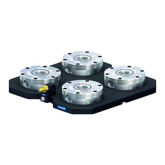
- Page 1 Translation of Original Operating Manual VERO-S quick-change pallet system NST3 Assembly and Operating Manual Superior Clamping and Gripping...
- Page 2 Imprint Copyright: This manual is protected by copyright. The author is SCHUNK GmbH & Co. KG. All rights reserved. Any reproduction, processing, distribution (making available to third parties), translation or other usage - even excerpts - of the manual is especially prohibited and requires our written approval.
-
Page 3: Table Of Contents
Table of Contents Table of Contents 1 General ........................5 1.1 About this manual ....................5 1.1.1 Presentation of Warning Labels ..............5 1.1.2 Applicable documents ................... 6 1.1.3 Sizes ....................... 6 1.2 Warranty ........................6 1.3 Scope of delivery ...................... 6 1.4 Accessories ....................... - Page 4 Table of Contents 4.5 VERO-S tombstones (optional) ................29 4.6 Screw tightening torques ..................30 5 Function ........................31 5.1 Connections on the clamping station..............31 5.2 Unlocking connection ..................... 32 5.3 TURBO connection ....................33 5.4 VERO-S connecting strip ASL2-G1/8” (optional) ............ 34 6 Operation ........................
-
Page 5: General
General General About this manual This manual contains important information for a safe and appropriate use of the product. This manual is an integral part of the product and must be kept accessible for the personnel at all times. Before starting work, the personnel must have read and understood this operating manual. -
Page 6: Applicable Documents
NSE3 * • Assembly and Operating Manual for VERO-S tombstone VAT / VAT3 * The documents marked with an asterisk (*) can be downloaded on our homepage schunk.com 1.1.3 Sizes This operating manual applies to the following sizes: Clamping station •... -
Page 7: Accessories
General Accessories (see catalog or data sheets when ordering separately) • VAT-AE, VAT-DR, VAT-DW, VAT3-AE, VAT3-DR, VAT3-DW tombstones • SAT tombstones • SAT NSF plus tombstones • SPA, SPB, SPC, SPG clamping pins • SDE protection cover • ASL2-G1/8“ connecting strip •... -
Page 8: Basic Safety Notes
Implementation of structural changes By conversions, changes, and reworking, e.g. additional threads, holes, or safety devices can impair the functioning or safety of the product or damage it. • Structural changes should only be made with the written approval of SCHUNK. 01.00|1344367_NST3 |en... -
Page 9: Spare Parts
Use of unauthorized spare parts Using unauthorized spare parts can endanger personnel and damage the product or cause it to malfunction. • Use only original spare parts or spares authorized by SCHUNK. Environmental and operating conditions Required ambient conditions and operating conditions... -
Page 10: Personal Protective Equipment
Basic safety notes The following personal qualifications are necessary for the various activities related to the product: Qualified personnel Due to its technical training, knowledge and experience, qualified personnel is able to perform the delegated tasks, recognize and avoid possible dangers and knows the relevant standards and regulations. -
Page 11: Notes On Safe Operation
Basic safety notes Notes on safe operation Incorrect handling of the personnel Incorrect handling and assembly may impair the product's safety and cause serious injuries and considerable material damage. • Avoid any manner of working that may interfere with the function and operational safety of the product. -
Page 12: Malfunctions
• Follow local regulations on dispatching product components for recycling or orderly disposal. • Dispose of the clamping station's metal parts as scrap metal. Alternatively, you can return it to SCHUNK for proper disposal. 2.12 Fundamental dangers General •... -
Page 13: Protection During Handling And Assembly
Basic safety notes 2.12.1 Protection during handling and assembly Incorrect handling and assembly Incorrect handling and assembly may impair the product's safety and cause serious injuries and considerable material damage. • Have all work carried out by appropriately qualified personnel. •... -
Page 14: Protection Against Dangerous Movements
Basic safety notes 2.12.3 Protection against dangerous movements Unexpected movements Residual energy in the system may cause serious injuries while working with the product. • Switch off the energy supply, ensure that no residual energy remains and secure against inadvertent reactivation. •... - Page 15 Basic safety notes WARNING Risk of injury due to falling tombstone, pallet or workpiece if the clamping pin locking is loosened from the clamping bolt mounting erroneously or as a result of negligence. • During operation, incorrect or negligent loosening of the clamping pin must be prevented using suitable countermeasures (disconnecting the power supply after locking, use of check valves or safety switches).
- Page 16 Basic safety notes CAUTION Risk of injury due to impurities (e.g. metal chips) in the exhaust and air purge connections of the clamping station. • Take appropriate protective measures to secure the danger zone. • Wear personal protective equipment (safety goggles). CAUTION Risk of injury due to compressed air hoses coming loose when connected improperly.
- Page 17 Basic safety notes CAUTION Danger due to pneumatic exhaust noises. Noise pollution from the exhaust system and whistling pneumatic equipment during the working process. • Wear hearing protection. 01.00|1344367_NST3 |en...
-
Page 18: Technical Data
Technical data Technical data Type ID no. Holding force* Fmax ** FmaxT *** Weight designation (M10 / M12 / M16) Total pull- Total pull- in force in force without with turbo turbo NST3 400-250 1337138 140 kN / 200 kN / 300 32 kN 112 kN 52 kg... -
Page 19: Assembly
Assembly Assembly General Installation Notes Pre-assembly measures Lift the quick-change pallet system carefully out of the packaging (e.g. using suitable lifting equipment). Eye bolts are supplied for transporting the clamping station. The eye bolts are to be mounted into the transport threads on the base plate and then removed after assembly. -
Page 20: Alignment Using Alignment Elements
Assembly Alignment using T-nuts 4.2.2 Alignment using alignment elements The clamping station can be mounted on the machine table via a centering pin for the center bore. The clamping station is aligned at an angle in a suitable alignment hole or alignment groove of the machine table via an adjustment pin, an adjustment pin with alignment width or a T-slot, and all six degrees of freedom are completely fixed. -
Page 21: Mounting And Connecting The Clamping Station
Assembly Mounting and connecting the clamping station To prevent chip accumulation, a sufficient number of protective covers for covering the mounting screws is provided in the accessory pack. WARNING Risk of injury due to brass bore hole cover plate ejecting during a turning application of the clamping station. - Page 22 Assembly ensure secure mounting, the clamping station must be fastened on the machine table at all possible mounting points. With the NST3 500-300, the clamping modules mounted must be removed prior to assembly in order to make the outer mounting locations accessible.
-
Page 23: Nst3 400-250
Assembly Number of clamping modules Min. nominal hose width (hose installed internal diameter) 6 mm 8 mm When decoupling hose lines, the pneumatic plug-in connection or the sealing nipple must be protected against the ingress of dirt or cooling lubricant. The sealing nipple comes with a plastic cover plug. -
Page 24: Nst3 500-300
Assembly NST3 400-250 4.3.2 NST3 500-300 The clamping station is mounted on the machine table with screws size M16 according to DIN EN ISO 4762 10.9. The mounting locations can also be screwed using M12 screws and suitable washers. There are two alignment grooves on the bottom of the clamping station for mounting loose T-nuts to be used for aligning the clamping stations. - Page 25 Assembly Note: The access to the outer mounting locations requires all four quick- change pallet modules to be disassembled. After the assembly of the clamping station, the modules have to be installed again with the required tightening torque. The scope of delivery includes new cover flaps for closing the fastening screws of the clamping modules.
-
Page 26: Clamping Pins Spa 40, Spb 40, Spc 40, Spg 40
If clamping pins are used outside of SCHUNK pallets, for example in customer-specific devices or workpieces, the outer diameter of the part to be clamped must be large enough to completely cover the flat sealing ring on the top of all quick-change pallet systems involved in the clamping function. - Page 27 Assembly Tolerances and installation conditions Type ID no. SPA 40 0471151 > 12 > 17 > 15 > 20 >12 SPB 40 0471152 > 12 > 17 > 15 > 20 >12 SPC 40 0471153 > 12 > 17 > 15 >...
-
Page 28: Information To Clamping Pin Spg 40
Assembly Clamping pallet with 4 clamping areas 4.4.1 Information to clamping pin SPG 40 Instead of the SPA 40, the SPG 40 can be used with a clamping area. The repeat accuracy increases to < 0.002 mm when using the SPG When connecting the screws from above, according to order preference 2, an M12 screw 10 mm longer of strength class 12.9 must be used. -
Page 29: Vero-S Tombstones (Optional)
Assembly VERO-S tombstones (optional) Suitable VERO-S tombstones are available as accessories for clamping stations. There are different sized tombstones that correspond to the clamping stations. These are available in the pallet sizes 400 x 400 mm and 500 x 500 mm. The tombstones can be equipped with VERO-S zero point clamping pins, thus achieving a highly precise change-repeat accuracy together with the clamping station. -
Page 30: Screw Tightening Torques
Assembly Screw tightening torques Tightening torques for mounting clamping pins to the workpiece or to the clamping pallet. (Screw quality 12.9) Screw size M10 M12 M14 M16 Tightening torques (Nm) Tightening torque for mounting the clamping station and for reinstalling clamping modules with fixing screws DIN EN ISO 4762. -
Page 31: Function
Function Function The VERO-S NST3 clamping station guarantees rapid changing of VERO-S tombstones, clamping pallets, devices or workpieces in the machine room with a high level of repeat accuracy. In the VERO-S quick-change pallet modules, the clamping pallet is positioned and locked with a high level of repeat accuracy via the related VERO-S clamping pin. -
Page 32: Unlocking Connection
Function Unlocking connection If the unlocking connection on the clamping station is pressurized with compressed air, all modules are unlocked simultaneously. Tombstones, clamping pallets, devices and workpieces can be exchanged or removed from the clamping station. Since VERO-S NSE3 clamping modules are spring-operated clamping systems, the connection must remain pressurized with compressed air (at least 5 bar) during the set-up / changing process. -
Page 33: Turbo Connection
Function TURBO connection The clamping stations are equipped with an additional turbo connection. When compressed air is applied at the connection for the turbo function, this function actively provides air pressure to support the spring-actuated locking procedure of the quick-change pallet module. -
Page 34: Vero-S Connecting Strip Asl2-G1/8" (Optional)
Function VERO-S connecting strip ASL2-G1/8” (optional) Upon customer request, a VERO-S connecting strip type ASL2 G1/8" can be mounted to the clamping station in order to facilitate access to the air supply points. The connecting strip is equipped with an elevated connection point with two size NW 7.4 sealing nipples. -
Page 35: Operation
In this case, the system must be inspected and damaged parts must be replaced immediately. Only original SCHUNK spare parts may be used! WARNING Risk of injury due to losing pallets or workpieces in the case of incorrect actuation caused by incorrect operation. -
Page 36: Maintenance And Care
Risk of injury and risk of damage to the clamping module when opening the housing cover. If the clamping module has to be disassembled, send the module to SCHUNK for repair. The covers of the clamping modules are spring preloaded and may only be removed by trained specialist personnel. The... -
Page 37: Leak Test
Maintenance and care • During maintenance work on the quick-change pallet modules or the bottom air supply of the clamping station, new seals must be fitted and lubricated with Renolit HLT 2 or a similar grease before assembly. • Check the supply hose line to the pressure supply of the clamping station for damage at regular intervals. -
Page 38: Troubleshooting
Defective air connections Check air supply Pressure below minimum Check operating pressure (min. 5 bar) A component is broken (e.g. due to Replace the module or send it to SCHUNK for overloading) repair Excess tensile load on clamping pins Reduce support weight... -
Page 39: Parts Lists
Parts lists Parts lists Part lists NST3 400-250 (ID. 1337138) Item Description Quantity Base plate M12 cover to close the bore M16 cover to close the bore M18 cover to close the bore Sealing ring G1/8" Sealing nipple G1/8" O-ring VERO-S NSE3 138 Eye bolt DIN 580 M12 NST3 500-300 (ID. -
Page 40: Assembly Drawing
Assembly drawing Assembly drawing NST3 400-250 01.00|1344367_NST3 |en... -
Page 41: Translation Of Original Declaration Of Incorporation
Translation of original declaration of incorporation in terms of the Directive 2006/42/EG, Annex II, Part 1.B of the European Parliament and of the Council on machinery. Manufacturer/ H.-D. SCHUNK GmbH & Co. Spanntechnik KG Distributor Lothringer Str. 23 D-88512 Mengen... -
Page 42: Appendix On Declaration Of Incorporation, As Per 2006/42/Ec, Annex Ii, No. 1 B
Appendix on Declaration of Incorporation, as per 2006/42/EC, annex II, No. 1 B Appendix on Declaration of Incorporation, as per 2006/42/EC, annex II, No. 1 B 1. Description of the basic safety and health protection requirements, as per 2006/42/EC, Annex I, that apply to and are fulfilled for the scope of the partly completed machinery: Product designation VERO-S clamping station Type designation... - Page 43 Appendix on Declaration of Incorporation, as per 2006/42/EC, annex II, No. 1 B 1.4.2.2 Interlocking movable guards 1.4.2.3 Adjustable guards restricting access 1.4.3 Special requirements for protective devices Risks due to other hazards 1.5.1 Electricity supply 1.5.2 Static electricity 1.5.3 Energy supply other than electricity 1.5.4 Errors of fitting...
Need help?
Do you have a question about the NST3 series and is the answer not in the manual?
Questions and answers