Table of Contents
Advertisement
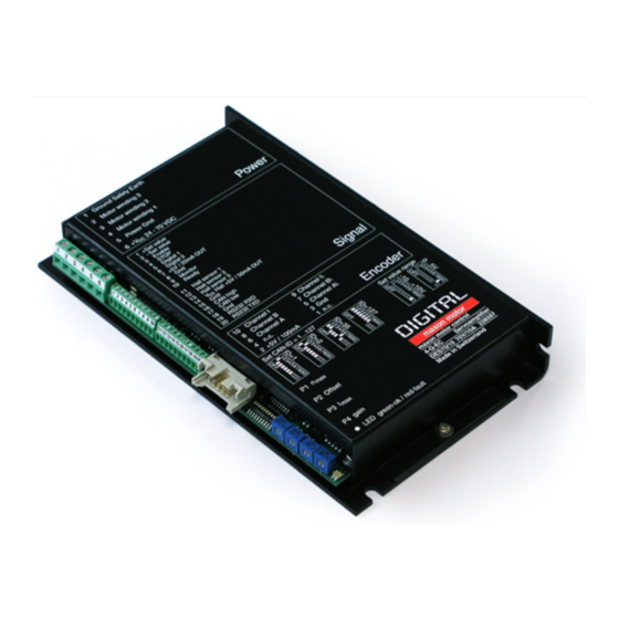
maxon motor control
Operating Instructions
The DES (Digital EC Servoamplifier) is a very efficient digital
servoamplifier with sinusoidal current commutation for
perfectly controlling EC (Electronic Commutation) motors.
The EC motors must be equipped with Hall sensors and a
digital encoder with line driver.
Control, monitoring and complete control algorithms are
carried out in a very fast digital signal processor.
As with classic, conventional automatic controllers, easy
trimming and adjustment of the servoamplifier is possible,
with just a few potentiometers.
As an alternative, configuration is also possible using a
PC (RS232 or CAN). This is particularly beneficial with
series application, as all adjustments and parameters can
be set quickly, numerically and easily reproduced.
The set value specification can be made conventionally
with an analogue input (0 ... 5 V or ±10 V), RS232 or CAN
bus interface.
The sinusoidal commutation causes minimal torque ripple
and low motor noise.
Table of Contents
1
Safety Instructions ...........................................................................................................................................2
2
Performance Data............................................................................................................................................3
3
Minimum External Wiring for Different Modes of Operation ............................................................................4
4
Operating Instructions......................................................................................................................................5
5
Functions..........................................................................................................................................................7
6
Error Messages..............................................................................................................................................15
7
EMC-compliant installation ............................................................................................................................16
8
Block Diagram................................................................................................................................................18
9
Dimension Drawing........................................................................................................................................18
The latest edition of these operating instructions, additional documentation and software to the DES 70/10 may also be found
on the Internet under
www.maxonmotor.com
This document is valid for the HardwareVersion 4102.
maxon motor
4-Q-EC Servoamplifier DES 70/10
category «Service & Downloads», Order number 228597.
Order number 228597
April 2006 Edition
Advertisement
Table of Contents

Related Manuals for maxon motor 4-Q-EC


Summary of Contents for maxon motor 4-Q-EC
-
Page 1: Table Of Contents
4-Q-EC Servoamplifier DES 70/10 Order number 228597 Operating Instructions April 2006 Edition The DES (Digital EC Servoamplifier) is a very efficient digital servoamplifier with sinusoidal current commutation for perfectly controlling EC (Electronic Commutation) motors. The EC motors must be equipped with Hall sensors and a digital encoder with line driver. -
Page 2: Safety Instructions
4-Q-EC Servoamplifier DES 70/10 Operating Instructions Safety Instructions Skilled Personnel Installation and starting of the equipment shall only be performed by experienced, skilled personnel. Statutory Regulations The user must ensure that the servoamplifier and the components belonging to it are assembled and connected according to local statutory regulations. -
Page 3: Performance Data
Operating Instructions 4-Q-EC Servoamplifier DES 70/10 Performance Data 2.1 Electrical Data Supply voltage V (Ripple < 5%)................24 - 70 VDC Max. output voltage......................0.9 · V Max. output current Imax ......................30 A Continuous output current Icont ....................10 A Switching frequency...................... -
Page 4: Minimum External Wiring For Different Modes Of Operation
4-Q-EC Servoamplifier DES 70/10 Operating Instructions Minimum External Wiring for Different Modes of Operation maxon motor control April 2006 Edition / Subject to change... -
Page 5: Operating Instructions
Operating Instructions 4-Q-EC Servoamplifier DES 70/10 Operating Instructions 4.1 Power supply layout Any available power supply can be used, provided it meets the minimal re- quirements set out below. During set up and adjustment phases, we recommend separating the motor mechanically from the machine to prevent damage due to uncontrolled motion. - Page 6 4-Q-EC Servoamplifier DES 70/10 Operating Instructions 4.3 Adjustment of the potentiometer 4.3.1 Pre-adjustment With the pre-adjustment, the potentiometers are set in a preferred position. DES units in the original packing are preset. Pre-adjustment potentiometers 30 % Offset 50 %...
-
Page 7: Functions
Operating Instructions 4-Q-EC Servoamplifier DES 70/10 Functions 5.1 Inputs 5.1.1 “Set value” Two different versions can be selected to give an analogue set value. Versions are selected by setting the DIP switch S9 “Set value range”. The “Set value” input is protected against overvoltage. - Page 8 4-Q-EC Servoamplifier DES 70/10 Operating Instructions 5.1.3 “Hall sensor 1”, “Hall sensor 2”, “Hall sensor 3” On one hand the Hall sensors detect the rotor position during start-up and on the other hand monitor the rotor position during operation.
- Page 9 Operating Instructions 4-Q-EC Servoamplifier DES 70/10 5.1.6 Toggle controller mode (speed/current control) “Digital 2” If the “Digital 2” input is not switched on (floating) or is connected to a voltage higher than 2.4 VDC, the servoamplifier is configured to speed controller mode.
- Page 10 4-Q-EC Servoamplifier DES 70/10 Operating Instructions 5.2 Outputs 5.2.1 Auxiliary voltage “V Hall +5 V / 50 mA OUT” An internal auxiliary voltage of +5 V is provided for powering the Hall sensors. The output is protected against overload.
- Page 11 Operating Instructions 4-Q-EC Servoamplifier DES 70/10 5.2.4 Status reading “Ready” The “Ready” signal can be used to report operational readiness or a fault condi- tion on a master control unit. The fault condition is stored. In order to reset the fault condition, the servoamplifier must be re-released (Enable).
- Page 12 4-Q-EC Servoamplifier DES 70/10 Operating Instructions 5.3 Interfaces 5.3.1 Serial Interface “RS232 RxD”, “RS232 TxD” Maximum input voltage ± 30 V ± 30 V Maximum output voltage Maximum bit rate 115 200 bit/s Data line protection ESD protected...
- Page 13 Operating Instructions 4-Q-EC Servoamplifier DES 70/10 5.3.3 CAN ID (CAN Identification) The CAN-ID (node address) is set at DIP switch S1 ... 7. All addresses can be coded from 1 ... 127 using the binary code. Switch Binary code...
- Page 14 4-Q-EC Servoamplifier DES 70/10 Operating Instructions 5.4 Current limit Brushless maxon EC motors are particularly well suited for use in servodrives. Very fast acceleration times and thermal overload protection are required. The digital servoamplifier DES 70/10 operates with I...
-
Page 15: Error Messages
Operating Instructions 4-Q-EC Servoamplifier DES 70/10 Error Messages 6.1 Faultless condition The green LED shows the operating status (“Enable” or “Disable”) of DES. DES in “Disable” status (DES ready): green LED flashes (flash frequency ap- prox. 1 Hz), red LED does not shine. -
Page 16: Emc-Compliant Installation
4-Q-EC Servoamplifier DES 70/10 Operating Instructions EMC-compliant installation Power supply (+V - Power Gnd) • No shielding normally required • Star point-shaped wiring if several amplifiers are supplied by the same power supply Motor cable (> 30 cm) •... - Page 17 Operating Instructions 4-Q-EC Servoamplifier DES 70/10 • See CiA DS-102 (twisted and / or shielded two-wire circuit closed with the cir- cuit’s impedance with common return circuit). • Closure with impedance through external circuit. • No galvanic separation on DES 70/10.
-
Page 18: Block Diagram
4-Q-EC Servoamplifier DES 70/10 Operating Instructions Block Diagram Ready +5V / 100mA +5V (2) Line +5V (1) +3.3V +5V / 20mA OUT Receiver +5V (1) Supply +5V (2) +12V green -12V +V 24 - 70VDC J403 +V Hall +5V / 50mA...
Need help?
Do you have a question about the 4-Q-EC and is the answer not in the manual?
Questions and answers