Table of Contents
Advertisement
Quick Links
maxon motor control
Operating Instructions
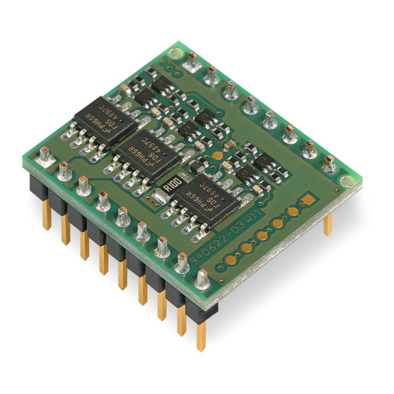
The DEC Module 24/2 (Digital EC Controller) is a small
1-quadrant digital controller for the control of brushless DC motors
(Electronic Commutated motors) up to 48 W.
The used EC motor must be equipped with digital Hall sensors.
Features:
•
Digital speed control
operates as «closed loop» or as «open loop» speed controller
•
Maximum speed 80 000 rpm (motor with 1 pole pair)
•
Set value input through external analogue voltage (0 ... +5 V)
•
3 different speed ranges selectable
•
Direction of rotation preset by a digital signal
•
The output stage can be enabled or disabled
•
Maximum output current limit adjustable up to 3 A
•
Status indication via «Ready»output
•
Blockage protection (current limit for blocked motor)
•
Protective functions: undervoltage, overvoltage and thermal overload
•
Standardized connector strip, pitch 2.54 mm
Thanks to the wide input power supply range of 8...24 VDC (optional 5 VDC operation possible), the DEC Module
24/2 is very versatile and can be used with various power supplies.
A sturdy PI speed controller design is an ideal premise for immediate operation.
The well-priced and miniaturized OEM module seamlessly integrates into applications. Now the customer can
fully focus on developing his/hers own device - while being able to make use of maxon motor's vast drive know-
how. For start-up maxon motor offers a comprehensive Evaluation Board.
Table of Contents
1 Safety Instructions ............................................................................................................................................. 2
2 Technical Data ................................................................................................................................................... 3
3 Pin assignment DEC Module 24/2 ..................................................................................................................... 5
4 Commissioning Instructions............................................................................................................................... 6
5 Functional Description of Inputs and Outputs.................................................................................................... 7
6 Protective functions ......................................................................................................................................... 13
7 Block Diagram ................................................................................................................................................. 14
8 Dimensional Drawing ....................................................................................................................................... 15
9 Accessories (not included in delivery) ............................................................................................................. 15
10 Appendix «Motherboard Design Guide» ....................................................................................................... 16
The latest edition of these operating instructions may be downloaded from the internet as a PDF-file under
www.maxonmotor.com, category «Service & Downloads», order number 367661 or
in the e-shop http://shop.maxonmotor.com.
maxon motor
1-Q-EC Amplifier DEC Module 24/2
Order number 367661
Edition April 2015
Advertisement
Table of Contents

Related Manuals for maxon motor 24/2


Summary of Contents for maxon motor 24/2
-
Page 1: Table Of Contents
The well-priced and miniaturized OEM module seamlessly integrates into applications. Now the customer can fully focus on developing his/hers own device - while being able to make use of maxon motor‘s vast drive know- how. For start-up maxon motor offers a comprehensive Evaluation Board. -
Page 2: Safety Instructions
1-Q-EC Amplifier DEC Module 24/2 Operating Instructions 1 Safety Instructions Skilled Personnel Installation and starting of the equipment shall only be performed by experi- enced, skilled personnel. Statutory Regulations The user must ensure that the amplifier and the components belonging to it are assembled and connected according to local statutory regulations. -
Page 3: Technical Data
Operating Instructions 1-Q-EC Amplifier DEC Module 24/2 2 Technical Data 2.1 Electrical data Nominal supply voltage +V ..............8 … 24 VDC (optional 5 VDC Absolute minimum supply voltage +V ............8 VDC (optional 5 VDC cc min Absolute maximum supply voltage +V .................. - Page 4 1-Q-EC Amplifier DEC Module 24/2 Operating Instructions 2.11 Standards The described device has been successfully tested for compliance with the below listed standards. In practical terms, only the complete system (the fully operational equipment comprising all individual components, such as motor, servo controller, power supply unit, EMC filter, cabling etc.) can undergo an...
-
Page 5: Pin Assignment Dec Module 24/2
Operating Instructions 1-Q-EC Amplifier DEC Module 24/2 3 Pin assignment DEC Module 24/2 Top view 3.1 Pin assignment Signal Description Signal Description Motor winding 1 Motor winding 2 Set value speed Set value speed input Motor winding 3... -
Page 6: Commissioning Instructions
Ö The power supply must be able to buffer the back-fed energy e.g. in a capacitor. The under voltage protection switches off the DEC Module 24/2, as soon Ö as the supply voltage V falls below 6.5 V. Therefore, at low supply vol-... -
Page 7: Functional Description Of Inputs And Outputs
Operating Instructions 1-Q-EC Amplifier DEC Module 24/2 5 Functional Description of Inputs and Outputs 5.1 Inputs 5.1.1 Speed range and mode selection with «DigIN1» und «DigIN2» The digital inputs «DigIN1» [11] and «DigIN2» [12] determine both, the ope- ration mode (digital speed controller or digital speed actuator) and the speed range in speed set value mode. - Page 8 1-Q-EC Amplifier DEC Module 24/2 Operating Instructions 5.1.2 Set value «Set value speed» At the «Set value speed» input [17] the external analogue set value and hence the rotational speed of the motor shaft is predetermined. By adjusting the signal levels on digital inputs «DigIN1 [11]» and «DigIN2 [12]»...
- Page 9 Operating Instructions 1-Q-EC Amplifier DEC Module 24/2 Adjusting set values via PWM control Instead of an analog voltage, a PWM signal with a fixed frequency and ampli- tude can be used to adjust the speed set value. The desired change in the set value is achieved by variation of the duty cycle in the range 0…100%.
- Page 10 1-Q-EC Amplifier DEC Module 24/2 Operating Instructions 5.1.3 «Enable» The «Enable» input enables or disables the power stage. If a voltage higher than 2.4 V is applied to the «Enable» input, the amplifier is activated (Enable). A speed ramp will be performed during acceleration.
- Page 11 Operating Instructions 1-Q-EC Amplifier DEC Module 24/2 5.1.5 «Set current limit» The «Set current limit» inputs is used for setting the contiunuous output cur- rent limitation in the range of 0.5...3 A. The current applied at the input «Set current limit» will stay available for an indefinite period of time.
- Page 12 1-Q-EC Amplifier DEC Module 24/2 Operating Instructions 5.2 Outputs 5.2.1 +5 VDC output voltage «V Hall» An internal auxiliary voltage of +5 VDC is provided for: Hall sensor supply voltage «V Hall» Ö For external set value potentiometer (recommended value: 10 k Ö...
-
Page 13: Protective Functions
Operating Instructions 1-Q-EC Amplifier DEC Module 24/2 6 Protective functions 6.1 Undervoltage protection The power stage will be disabled in case the supply voltage +V gets lower than 6.5 VDC. To reset the fault condition the amplifier must be disabled and the supply voltage +V must be higher than 6.5 VDC. -
Page 14: Block Diagram
1-Q-EC Amplifier DEC Module 24/2 Operating Instructions 7 Block Diagram maxon motor control April 2015 Edition / document number 1002422_PDF_E - 04 / subject to change... -
Page 15: Dimensional Drawing
Operating Instructions 1-Q-EC Amplifier DEC Module 24/2 8 Dimensional Drawing Dimensions in [mm] 9 Accessories (not included in delivery) maxon motor order number Designation 370652 DEC Module Evaluation Board April 2015 Edition / document number 1002422_PDF_E - 04 / subject to change... -
Page 16: Appendix «Motherboard Design Guide
10.1 Introduction The present documentation «Motherboard Design Guide» contains helpful information on the integration of the DEC Modules 24/2 into printed circuit boards. Contained therein are recommendations for possibly needed 3rd par- ty components, suggestions on layout, terminal assignment as well as circuit samples. - Page 17 Operating Instructions 1-Q-EC Amplifier DEC Module 24/2 Fuse FU1: To protect against reverse polarity, place a fuse at the entry of the power supply. Together with the TVS-diode, the fuse breaks an occurring reverse current. The continuous current of the fuse depends on the number of the DEC modules supplied and how much current each module needs.
- Page 18 1-Q-EC Amplifier DEC Module 24/2 Operating Instructions 10.2.3 Motor phase The DEC Module 24/2 has no built-in choke per phase. For the most motors and applications no additional motor chokes are neces- sary. In case of high power supply voltage +V...
- Page 19 1-Q-EC Amplifier DEC Module 24/2 10.3 Design rules To help customers designing an application specific motherboard and for correct and save function of the DEC Module 24/2 these rules can be followed. 10.3.1 Ground The ground (Gnd) pins of the DEC Module are internally connected (same electrical potential).
- Page 20 Hall sensor 3 10.8.2 Low Voltage +5V operation Alternatively, the DEC Module 24/2 can be operated with a supply voltage of +5 VDC (±5 %). Thereby, the external +5 VDC power source must be con- nected to pin [4] «+V »...
- Page 21 1-Q-EC Amplifier DEC Module 24/2 10.8.3 Maximum external wiring according to the DEC Module Evaluation Board order number 370652 For initial commissioning, maxon motor offers an Evaluation Board for a single-axis system. The motherboard «DEC Module Evaluation Board» can be ordered with order number 370652.
- Page 22 1-Q-EC Amplifier DEC Module 24/2 Operating Instructions Picture of Evaluation Board with DEC Module 24/2: maxon motor control April 2015 Edition / document number 1002422_PDF_E - 04 / subject to change...
Need help?
Do you have a question about the 24/2 and is the answer not in the manual?
Questions and answers