JLG AM Series Service And Maintenance Manual
Hide thumbs
Also See for AM Series:
- Service and maintenance manual (62 pages) ,
- Operation and safety manual (78 pages)

Related Manuals for JLG AM Series


Summary of Contents for JLG AM Series
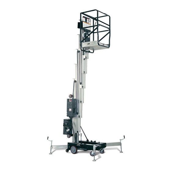
- Page 1 Service and Maintenance Manual Model(s) AM Series 20AM 25AM 30AM 36AM 41AM 3120752 June 29, 2018 - Rev N...
- Page 3 TRIES, INC. OR THE LOCAL AUTHORIZED JLG DISTRIBUTOR FOR INFORMATION CONCERNING SAFETY RELATED BULLE- TINS WHICH MAY HAVE BEEN ISSUED FOR YOUR JLG PRODUCT. ALL ITEMS REQUIRED BY THE SAFETY RELATED BULLETINS MUST BE COMPLETED ON THE AFFECTED JLG PRODUCT.
- Page 4 NOTES:...
-
Page 5: Introduction - Operation/Safety Precautions
Nor shall the listing of these requirements platform, except in case of an emergency. constitute an assumption of responsibility of liability on the part of JLG Industries, Inc. 11. Regular inspection of the job site and aerial lift shall be performed by competent persons. -
Page 6: Introduction - Maintenance Safety Precautions
2. Relieve system pressure by activating the lift DOWN control with the platform completely lowered to direct any line pressure back into the return line to the reservoir. Pressure feed lines to system compo- nents can then be disconnected with minimal fluid loss. – JLG Lift – 3120752... -
Page 7: Effectivity Changes
July 11, 2006 - J - Manual Revised January 30, 2008 - K - Manual Revised August 29, 2012 - L -Manual Revised April 2, 2013 - M - Manual Revised June 29, 2018 - N - Revised Covers 3120752 – JLG Lift –... - Page 8 EFFECTIVITY PAGE NOTES: – JLG Lift – 3120752...
-
Page 9: Table Of Contents
Bearings ..............2-5 3120752 – JLG Lift –... - Page 10 Mast Section 2 - Assembly (All Masts) ......... 2-24 – JLG Lift –...
- Page 11 Detent Screws ............3-10 3120752 – JLG Lift –...
- Page 12 Hydraulic Schematic. (AM Series) (2792491_A)........
-
Page 13: Section 1 - Specifications
36AM-AC - 1,060 lbs. (481kg) Pressure Relief – Adjustable Range 1500 to 5000 PSI, 36AM-DC - 1,160 lbs. (526kg) Set to 2800 PSI (193 bar) at factory 41AM-AC - 1,100 lbs. (499kg) 41AM-DC - 1,230 lbs. (558kg) 3120752 – JLG Lift –... -
Page 14: Machine Height (Platform Stowed)
Mobil DTE 13 hydraulic oil. Maximum Working Height (Average Person) Aside from JLG recommendations, it is not advisable to 20AM-AC & DC - 26 ft. (7.92m) mix oils of different brands or types, as they may not con- 25AM-AC &... -
Page 15: Hydraulic Pressure Adjustment
OIL TANK GROUND CONTROL ST A TION COVER Figure 1-1. Hydraulic Pressure Setting - Adjustment Screw Located at Base of Pump Motor (Remove Hex Head Cap as Shown) 3120752 – JLG Lift –... - Page 16 4. Prior to checking hydraulic oil level, operate machine through one complete cycle of lift function (full up and down). Failure to do so will result in incorrect oil level reading on the hydraulic reservoir. <--- START HERE - COPY AND PASTE – JLG Lift – 3120752...
-
Page 17: Torque Chart
1. THESE TORQUE VALUES DO NOT APPLY TO CADMIUM PLATED FASTENERS 2. ALL TORQUE VALUES ARE STATIC TORQUE MEASURED PER STANDARD AUDIT METHODS TOLERANCE = ±10% 3. * ASSEMBLY USES HARDENED WASHER REFERENCE JLG ANEROBIC THREAD LOCKING COMPOUND JLG P/N Loctite® P/N... - Page 18 1. THESE TORQUE VALUES DO NOT APPLY TO CADMIUM PLATED FASTENERS 2. ALL TORQUE VALUES ARE STATIC TORQUE MEASURED PER STANDARD AUDIT METHODS TOLERANCE = ±10% 3. * ASSEMBLY USES HARDENED WASHER Figure 1-3. Torque Chart (SAE Fasteners - Sheet 2 of 7)) – JLG Lift – 3120752...
- Page 19 4. CLAMP LOAD LISTED FOR SHCS IS SAME AS GRADE 8 OR CLASS 10.9 AND DOES NOT REPRESENT FULL STRENGTH CAPABILITY OF SHCS. IF HIGHER LOAD IS REQUIRED, ADDITIONAL TESTING IS REQUIRED. Figure 1-4. Torque Chart (SAE Fasteners - Sheet 3 of 7) 3120752 – JLG Lift –...
- Page 20 4. CLAMP LOAD LISTED FOR SHCS IS SAME AS GRADE 8 OR CLASS 10.9 AND DOES NOT REPRESENT FULL STRENGTH CAPABILITY OF SHCS. IF HIGHER LOAD IS REQUIRED, ADDITIONAL TESTING IS REQUIRED. Figure 1-5. Torque Chart (SAE Fasteners - Sheet 4 of 7) – JLG Lift – 3120752...
- Page 21 4. CLAMP LOAD LISTED FOR SHCS IS SAME AS GRADE 8 OR CLASS 10.9 AND DOES NOT REPRESENT FULL STRENGTH CAPABILITY OF SHCS. IF HIGHER LOAD IS REQUIRED, ADDITIONAL TESTING IS REQUIRED. Figure 1-6. Torque Chart (METRIC Fasteners - Sheet 5 of 7)) 3120752 – JLG Lift –...
- Page 22 4. CLAMP LOAD LISTED FOR SHCS IS SAME AS GRADE 8 OR CLASS 10.9 AND DOES NOT REPRESENT FULL STRENGTH CAPABILITY OF SHCS. IF HIGHER LOAD IS REQUIRED, ADDITIONAL TESTING IS REQUIRED. Figure 1-7. Torque Chart (METRIC Fasteners - Sheet 6 of 7) 1-10 – JLG Lift – 3120752...
- Page 23 4. CLAMP LOAD LISTED FOR SHCS IS SAME AS GRADE 8 OR CLASS 10.9 AND DOES NOT REPRESENT FULL STRENGTH CAPABILITY OF SHCS. IF HIGHER LOAD IS REQUIRED, ADDITIONAL TESTING IS REQUIRED. Figure 1-8. Torque Chart (METRIC Fasteners - Sheet 7 of 7) 3120752 – JLG Lift – 1-11...
- Page 24 SECTION 1 - SPECIFICATIONS NOTES: 1-12 – JLG Lift – 3120752...
-
Page 25: Section 2 - Service Procedures
The Annual Machine Inspection must be performed by a machine into service. qualified JLG equipment mechanic on an annual basis, no Preparation, Inspection, and Maintenance later than thirteen (13) months from the date of the prior Annual Machine Inspection. -
Page 26: Preventive Maintenance And Inspection Schedule
Owner, Dealer, or User Qualified JLG Service and Maintenance Man- Inspection rental delivery. Mechanic ual and applicable JLG inspec- tion form. Frequent In service for 3 months or 150 hours, Owner, Dealer, or User Qualified JLG Service and Maintenance Man- Inspection whichever comes first;... - Page 27 Hydraulic Cylinder 7, 9 2, 9 2, 9 Cylinder Attachment Pins and Pin Retainers 1, 2 Hydraulic Hoses, Lines, and Fittings 1, 9 Hydraulic Reservoir, Cap, and Breather 5, 7 5, 7 5, 7 Hydraulic Filter 3120752 – JLG Lift –...
- Page 28 Grease and Lubricate to Specifications Function Test of All Systems Paint and Appearance Stamp Inspection Date on Frame Notify JLG of Machine Ownership * Change per Lubrication Chart in Section-1 of this Service Manual. Footnotes: 9. Check for signs of leakage.
-
Page 29: Servicing And Maintenance Guidelines
New parts and thickness. Be sure to cut holes in the right location, as should remain in their containers until they are ready to be blank gaskets can cause serious system damage. used. 3120752 – JLG Lift –... -
Page 30: Bolt Usage And Torque Application
Fatigue and ultimate strength failures on JLG Lifts are incurred as a result of severe abuse as design specs are well within the rated lift- ing capacity of these chains. -
Page 31: Mast Cable Inspection Procedure
Inspection should be more frequent as cables approach the end of their useful lives. Only the surface wires of the cable require inspection, do not attempt to open the cable. Any deterioration resulting 3120752 – JLG Lift –... -
Page 32: Lubrication Information
Hydraulic Oil For best performance, JLG recommends the use of ISO- Vg grade 32, 46 oil with a viscosity range between 15-250 SUS at 100 degrees F (32-54 cST at 40 degrees C). Refer to Section 7 for recommended hydraulic oils. -
Page 33: Battery Charger - Assembly And Disassembly
MODEL CHARGER ARE ALSO INCLUDED IN THE MANUFACTUR- ERS (SCR) BATTERY CHARGER MANUAL The AM Series dual AC input battery charger allows for replacement of the following internal components. Con- sult your Illustrated Parts Manual for part numbers of... -
Page 34: Transformer Replacement
3. Remove transformer. DC Circuit Breaker Replacement 1. Remove the wiring from the breaker terminals. 2. Remove the bolt, nut and washer from each side of the breaker, remove the breaker from the housing. 2-10 – JLG Lift – 3120752... -
Page 35: Ac Circuit Breaker And Voltage Selection Switch Replacement
(see illustration below). One through the rear panel of the base with a short white spacer and one at the long white insulator attaching the shunt assembly to the bracket. 2. Remove the varistor from it’s mount. 3120752 – JLG Lift – 2-11... -
Page 36: Hydraulic Lift Pump - Servicing
1. Motor Assembly 3. Pump End Head 2. Positive (+) Post 4. Spring Washer 2. Motor Assembly Screws 4. Motor to Pump Coupler Note: Length of wires to brush assemblies shown exaggerated for illustrative purposes. 2-12 – JLG Lift – 3120752... -
Page 37: Brush Housing Final Assembly Tips
Clean the rotor commutator with a non-conductive electrical CONTACT WITH THE COMMUTATOR ON THE ROTOR SHAFT cleaner before assembling the brush housing to the motor hous- AND THE BRUSH SPRING IS PUSHING DOWN ON TOP OF ing. THE BRUSH. 3120752 – JLG Lift – 2-13... -
Page 38: Monarch Brand Pump - Brush Replacement
NOTE: (a) Once cover screws are removed, you may need to tap lightly around the edge of the top cover to separate it from the motor housing. Read the important note above before attempting to remove the cover. (b) These steel screws are threaded into the aluminum valve body, do not overtighten. 2-14 – JLG Lift – 3120752... -
Page 39: Brush Carrier Assembly - Remove/Install
1. Brush Assembly (a) 4. Brush Terminal Screw 2. Brush Carrier Socket 5. Brush Attach Terminal 3. Brush Tab Slot NOTE: (a) Slide brush assembly into socket until tab is in slot at rear of socket. 3120752 – JLG Lift – 2-15... -
Page 40: Tank And Pump Removal - (All Pumps)
4. Use Screwdriver to pry tank away from pump head. Filter Screen Installation Filter Screen Installation 1. Filter Screen 2. Pump Pick-Up Tube Pump O-Ring Installation 1. Pump Assembly 2. O-Ring Seal 3. O-Ring Seal 2-16 – JLG Lift – 3120752... -
Page 41: Pressure Adjust Valve Installation
6. Extend (Pressure) Port 3. O-Ring Seal 7. Return Port (Shown Plugged) 4. Backing Ring Note: Adjust pressure per specification shown in Section-1 of this Note: Extend (Pressure) and Return Ports Shown Plugged Service Manual. 3120752 – JLG Lift – 2-17... -
Page 42: Hydraulic Lift Cylinder - Removal, Inspection And Rebuild
Remove the rod seal, static o-ring and 11. Pull the mast cylinder out of the mast. backup and rod wiper. Damage to the seal grooves, par- ticularly on the sealing surfaces, is unacceptable. In the 2-18 – JLG Lift – 3120752... -
Page 43: Lift Cylinder Internal Component Assembly Cross-Section
Remove the seals and bearings. Damage to the seal grooves, particularly on the sealing surfaces, is unacceptable. In the event that an unacceptable condition occurs, the piston should be replaced. 3120752 – JLG Lift – 2-19... -
Page 44: Cylinder Assembly
14. Install the ground station (pump) cover. 15. Set-up machine for operation and cycle mast (up and down) approximately 3 ft. to 4 ft. a few times. 16. Check the hydraulic oil reservoir again, add oil to the fill line. 2-20 – JLG Lift – 3120752... -
Page 45: Mast Assembly And Disassembly Procedures
(See Figure 2-2.). Always install slide pad shims with slide pads inserted into the slide pad channels, The AM Series personnel lift mast sections are con- (ends of mast sections even). Shim slide pads so that all... -
Page 46: Platform Section Removal (All Masts)
20 ft. mast, go to step 17. scratch or score the anodized finish in the slide pad channels. 11. Remove cable adjust nuts from threaded ends of cable attached to the cable anchor plate on bottom 2-22 – JLG Lift – 3120752... -
Page 47: Mast Section 3 Removal (All Masts)
32. Remove the setscrew holding the hydraulic cylinder rod into the chain assembly anchor block. Lay chain assembly to side. NOTE: When sliding mast sections apart, be careful not to scratch or score the anodized finish in the slide pad channels. 3120752 – JLG Lift – 2-23... -
Page 48: Mast Assembly
Align the hole in the mounting journal with the shim and mast or shim and slide pad when tight- hole in the cylinder and Install the (1) 5/16" bolt. ened. 2-24 – JLG Lift – 3120752... -
Page 49: 20Am Mast Assembly Components. (5 - Section)
SECTION 2 - SERVICE PROCEDURES ORIGINAL DESIGN LIFT CYLINDER MOUNT NEW DESIGN LIFT CYLINDER AND MOUNT Figure 2-3. 20AM Mast Assembly Components. (5 - Section) 3120752 – JLG Lift – 2-25... -
Page 50: 25Am & 36Am Mast Assembly Components. (6 - Section)
POSITION PRIOR TO C# 142920 SECTION-6 UPPER LOWER SLIDE PAD SEQUENCE AS OF CABLE NEW DESIGN LIFT CYLINDER C# 142920 ASSEMBLY AND MOUNT Figure 2-4. 25AM & 36AM Mast Assembly Components. (6 - Section) 2-26 – JLG Lift – 3120752... -
Page 51: 30Am & 41Am Mast Assembly Components. (7 - Section)
TO SERIAL# 142920 30AM 41AM SECTION-7 LOWER UPPER SEQUENCE SLIDE PAD CABLE NEW DESIGN LIFT CYLINDER AS OF ASSEMBLY AND MOUNT SERIAL# 142920 Figure 2-5. 30AM & 41AM Mast Assembly Components. (7 - Section) 3120752 – JLG Lift – 2-27... -
Page 52: Mast Chain/Cable Routing Diagram
SECTION 2 - SERVICE PROCEDURES Figure 2-6. Mast Chain/Cable Routing Diagram. 2-28 – JLG Lift – 3120752... -
Page 53: Mast Section 3 - Assembly (All Masts)
(2) 1/4"-20UNC x 3/4" long slide pad inserts. Thread in enough to hold pad in bolts, place a flatwasher under head of each bolt. place. 3120752 – JLG Lift – 2-29... -
Page 54: Mast Section 4 - Assembly (All Masts)
Thread in enough to hold pad assemble cable sheaves to top of mast section-4 as in place. follows; 45. Shim per instructions in step 7, Mast Section 2 - Assembly. 2-30 – JLG Lift – 3120752... -
Page 55: Mast Section 5 - Assembly (25/30/36/41 Ft. Masts)
59. Shim per instructions in step 7, Mast Section 2 - sheave wheels onto sheave pin and center. Assembly. b. Place two (2) short spacer tubes on sheave pin, one on each end of sheave pin to outside of sheave wheels. 3120752 – JLG Lift – 2-31... -
Page 56: Mast Section 6 - Assembly (30/41 Ft. Masts)
20UNC x 3/4" long bolts, place a flatwasher under pad channels. head of each bolt. 66. Carefully slide mast section-6 back into section-5 until ends are even. Check to make sure cable set 2-32 – JLG Lift – 3120752... - Page 57 Begin sliding top of mast section-5/-6/-7 with closed rail down engaging the slide pads into slide pad channels at bottom of mast section-4/- 5/-6’s open rail. Continue to push section-5/-6/-7 into section-4/-5/-6 until BOTTOM ends of mast sections are even. 3120752 – JLG Lift – 2-33...
-
Page 58: Mast To Base Frame Installation
7. Attach mast to base using four (4) 3/8"-16UNC x 1" long hex head bolts, flatwashers, and nuts. (place a flatwasher under bolt head, mount with nuts on inside of frame). Apply Loctite #242 to bolt threads before final tightening of nuts. 2-34 – JLG Lift – 3120752... -
Page 59: Mast Chains/Cables And Sequencing Cables Adjustment
When chain adjustment JAM NUT is complete, before tightening the jam nut THREADED against the adjust nut, CHAIN/CABLE apply Loctite #242 to the threads under the jam nut. Figure 2-7. Mast Chain/Cable/Sequence Cable Adjustment Components. (Typical) 3120752 – JLG Lift – 2-35... -
Page 60: Sequencing Cable Adjustment
(adjust) nut. Chain/ cable should have slight tension but should not be taut. Run mast through several cycles to verify cable/chain adjustments and ensure no interference exists between chain anchor brackets and mast. 2-36 – JLG Lift – 3120752... -
Page 61: Sequence Cable Replacement Kit
THE MANUFACTURER OF THE DRUM/SOCKET CLAMP RECOM- sequence cable with the threaded (top) end attached MENDS THE USE OF THEIR CABLE CLAMP ASSEMBLY KIT (JLG same as the top end of the factory cable. Also included is P/N - 7023275) TO ASSEMBLE THE CLAMP TO THE WIRE ROPE. - Page 62 NOTE: The end of the rope may not be visible in the inspec- tion hole after loading. 9. Install cable on machine and adjust per instructions shown previously in Section 2.11, MAST CHAINS/ CABLES AND SEQUENCING CABLES ADJUST- MENT. 2-38 – JLG Lift – 3120752...
-
Page 63: Section 3 - Troubleshooting
For example, you can read the voltage applied to a solenoid when it is only operational while a switch, far from the solenoid and meter, is held down. 3120752 – JLG Lift –... -
Page 64: Polarity
1 through 4. If there is a prob- harness. lem the third wire is used to troubleshoot the other wires. • Meter that can measure resistance or continuity. To find the problem, start at step 1 and use the entire pro- cedure. – JLG Lift – 3120752... -
Page 65: Resistance Measurement
• Circuit power must be turned OFF before testing resistance • Disconnect component from circuit before testing • If meter is not auto ranging, set it to the correct range (See multimeter’s operation manual) • Use firm contact with meter leads 3120752 – JLG Lift –... - Page 66 (See multi meter’s operation manual) • Use firm contact with meter leads • Use firm contact with meter leads • First test meter and leads by touching leads together. Meter should produce an audible alarm, indicating continuity – JLG Lift – 3120752...
-
Page 67: Electrical Switch Testing
This voltage can be seen if the measurement Another type of limit switch used by JLG is the inductive is taken with one test lead on the load and the other on proximity switch, also referred to as a "prox switch". - Page 68 Breather cap on tank is saturated or Replace breather cap on tank. clogged with oil. Hydraulic oil tank over-filled. Lower oil level to full mark on dipstick. Unit lowers very slowly. Flow control valve not functioning. Replace flow control valve. – JLG Lift – 3120752...
- Page 69 Breather cap on tank is saturated or Replace breather cap on tank. clogged with oil. Hydraulic oil tank over-filled. Lower oil level to full mark on dipstick. Unit lowers very slowly. Flow control valve not functioning. Replace flow control valve. 3120752 – JLG Lift –...
-
Page 70: Outrigger Interlock Contacts
Install the screw with two (2) o-rings towards jack 3. Install two (2) #8 nylon washers onto contactor end of outrigger beam. Hold in place if necessary. screw threads against insulating grommet, on the underside of the outrigger socket. – JLG Lift – 3120752... -
Page 71: Outrigger Socket Contactor Heads And Outrigger Beam - Contactor Plate Mounting Hardware (Original And 5/2001 - Design)
NYLON W ASHERS OUTRIGGER SOCKET (FLOOR) OPEN END OF OUTRIGGER SOCKET APPL Y LOCTITE #242 TO THREADS Figure 3-5. Outrigger Socket Contactor Heads and Outrigger Beam - Contactor Plate Mounting Hardware (ORIGINAL AND 5/2001 - DESIGN). 3120752 – JLG Lift –... -
Page 72: Detent Screws
AM model to assure machine stability, i.e. the shorter outrigger beams of the 20AM, 25AM and 30AM models cannot be mistak- enly used on higher reaching 36AM or 41AM models. 3-10 – JLG Lift – 3120752... -
Page 73: Hydraulic Schematic. (Am Series) (2792491_A)
SECTION 3 - TROUBLESHOOTING 2792491_A Figure 3-6. Hydraulic Schematic. (AM Series) (2792491_A) 3120752 – JLG Lift – 3-11... -
Page 74: Electrical Diagram. (Am Series - 12V-Dc)
SECTION 3 - TROUBLESHOOTING 4933203_D Figure 3-7. Electrical Diagram. (AM Series - 12V-DC) 3-12 – JLG Lift – 3120752... - Page 75 SECTION 3 - TROUBLESHOOTING 4933203_D Figure 3-3. Electrical Diagram. (AM Series - 12V-DC) 3120752 – JLG Lift – 3-13...
- Page 76 SECTION 3 - TROUBLESHOOTING 4933204_K Figure 3-8. Electrical Diagram. (AM Series - 120V-AC) 3-14 – JLG Lift – 3120752...
- Page 77 SECTION 3 - TROUBLESHOOTING 4933204_K Figure 3-4. Electrical Diagram. (AM Series - 120V-AC) 3120752 – JLG Lift – 3-15...
- Page 78 SECTION 3 - TROUBLESHOOTING 4933205_K Figure 3-9. Electrical Diagram. (AM Series - 240V-AC) 3-16 – JLG Lift – 3120752...
- Page 79 SECTION 3 - TROUBLESHOOTING 4933205_K Figure 3-5. Electrical Diagram. (AM Series - 240V-AC) 3120752 – JLG Lift – 3-17...
- Page 80 SECTION 3 - TROUBLESHOOTING 4933206_C Figure 3-10. Electrical Diagram. (AM Series - 100V-AC - JAPAN) 3-18 – JLG Lift – 3120752...
- Page 81 SECTION 3 - TROUBLESHOOTING 4933206_C Figure 3-5. Electrical Diagram. (AM Series - 100V-AC - JAPAN) 3120752 – JLG Lift – 3-19...
- Page 82 SECTION 3 - TROUBLESHOOTING NOTES: 3-20 – JLG Lift – 3120752...
- Page 84 Corporate Office JLG Industries, Inc. 1 JLG Drive McConnellsburg, PA 17233-9533 USA (717) 485-5161 (Corporate) (877) 554-5438 (Customer Support) (717) 485-6417 Visit our website for JLG Worldwide Locations. www.jlg.com...
Need help?
Do you have a question about the AM Series and is the answer not in the manual?
Questions and answers