JLG 1230ES Service Maintenance Manual
Hide thumbs
Also See for 1230ES:
- Service and maintenance manual (204 pages) ,
- Operation and safety manual (96 pages) ,
- Operation & safety manual (92 pages)

Related Manuals for JLG 1230ES


Summary of Contents for JLG 1230ES
- Page 1 Service & Maintenance Manual 1230ES PVC 2202 31219983 June 7, 2024 - Rev B ANSI Copyright © AS NZS MOL 70...
- Page 3 HYDRAULIC SYSTEM SAFETY It should be noted that the machines hydraulic systems operate at extremely high potentially dangerous pressures. Every effort should be made to relieve any system pressure prior to disconnecting or removing any portion of the system. VE100247A 1230ES 31219983...
- Page 4 • USE ONLY REPLACEMENT PARTS OR COMPONENTS THAT ARE APPROVED BY JLG. TO BE CONSIDERED APPROVED, REPLACEMENT PARTS OR COMPONENTS MUST BE IDENTICAL OR EQUIVALENT TO ORIGINAL PARTS OR COMPONENTS.
- Page 5 REVISION LOG DATE REVISION DESCRIPTION February 14, 2022 Original Issue June 7, 2024 Revised 1230ES 31219983...
- Page 6 This Page is intentionally left blank...
- Page 7 Wheels And Tires - Drive And Rear..................53 Rear Wheel Hub - Installation .....................55 Steering Linkage Assembly - Installation ................56 Steer Cylinder - Servicing....................57 Drive Motor/Spindle Assembly - Installation .................62 Wheel Drive Assembly - Servicing ..................63 Hydraulic Pump/Motor/Valve Assembly - Service Procedure..........79 1230ES 31219983...
- Page 8 Platform Assembly ......................129 Mast Assembly........................ 132 Multi-Stage Hydraulic Cylinder - Servicing ................. 143 SECTION 7 JLG CONTROL SYSTEM........................151 Electronic Control System ....................151 Machine Configuration Programming Information .............. 163 Machine Personality - Adjustment Settings ................ 164 Tilt Sensor Calibration...................... 166 Tilt Sensor Electrical Evaluation..................
- Page 9 Machine Location Of Component X-Connectors ..............221 9.12 Electrical Layout And Schematics ..................223 9.13 Electrical Schematics....................... 226 9.14 Pin Input /Output Types....................230 9.15 AC Power Receptacles And Wiring (Platform) - CE/UKCA Spec Machines Only....233 9.16 Hydraulic Schematic......................236 1230ES 31219983...
- Page 10 This Page is intentionally left blank...
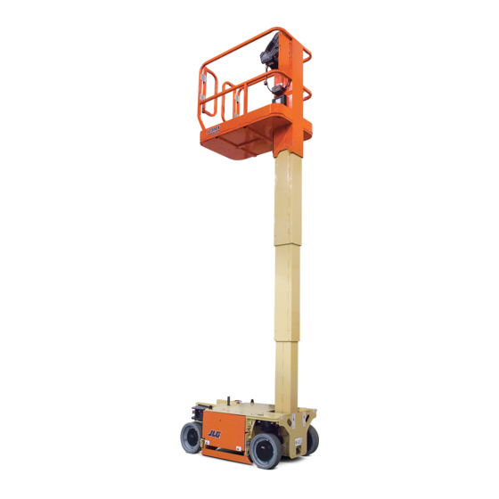
- Page 11 SECTION 1 MACHINE SPECIFICATIONS VE100109A OPERATING SPECIFICATIONS Description Model 1230ES Platform Maximum Platform Height 12 ft. (3.66 m) Driving Maximum Drive Speed Stowed: 3 mph (4.8 kph) Elevated: 0.5 mph (0.8 kph) Maximum Stowed Travel Grade (Gradeability) 25% (14°) Maximum Stowed Travel Grade (Side slope) 5°...
- Page 12 MACHINE SPECIFICATIONS Description Model 1230ES Approximate Gross Machine Weight - ANSI/CSA/CE/UKCA/AUS 1775 lb (805 kg) - ANSI/ANSI exp/CSA 1740 lb (789 kg) - CE/UKCA/JPN 2360 lb (1070 kg) - AUS w/CWT Maximum Tire Load (per wheel) 880 lb (400 kg)
- Page 13 MACHINE SPECIFICATIONS Description Model 1230ES Overall Stowed Machine Height 65.39 in. 166 cm 68.6 in.-AUS w/CWT 174.2 cm-AUS w/CWT Rail Height (From platform floor) 43.8 in. 111.2 cm Overall Machine Width 30 in. 76 cm Overall Machine Length 53.5 in.
- Page 14 If use of hydraulic oil other than premium hydraulic fluid is desired, contact JLG for proper recommendations.
- Page 15 (3). Check the oil level in the hydraulic reservoir by looking at the markings on the side of the tank. The reservoir is marked with MIN (minimum) and MAX (maximum) markings (4). The oil level must be within these markings to operate properly. 1230ES 31219983...
- Page 16 For machine identification, a metal serial number plate is affixed to the machine. The plate is mounted behind the left rear wheel on the side of the base frame. The machine serial number can also be found on a bar code label placed on the platform control station mounting plate in the platform. 31219983 1230ES...
- Page 17 MACHINE SPECIFICATIONS THREADLOCKING COMPOUND Description JLG PN Loctite® ND Industries Medium Strength (Blue) 0100011 242™ Vibra-TITE™ 121 Medium Strength (Blue) 1001095650 243™ Vibra-TITE™ 122 High Strength (Red) 0100019 271™ Vibra-TITE™140 Medium - High Strength (Red) 0100071 262™ Vibra-TITE™ 131 Note: Loctite®243™can be substituted in place of Loctite® 242™. Vibra-TITE™122 can be substituted in place of Vibra-TITE™...
- Page 18 0.3125 0.0524 3340 0.3125 0.0580 3700 0.3750 0.0775 4940 0.3750 0.0878 5600 7/16 0.4375 0.1063 6800 0.4375 0.1187 7550 0.5000 0.1419 9050 0.5000 0.1599 10700 9/16 0.5625 0.1820 11600 0.5625 0.2030 12950 0.6250 0.2260 14400 0.6250 0.2560 16300 31219983 1230ES...
- Page 19 2300 3128 1974 2676 5000059K NOTE- 1. These torque values do not apply to cadmium plated fasteners 2. All torque values are static torque measured per standard audit methods tolerance = ±10% 3. * Assembly uses hardened washer 1230ES 31219983...
- Page 20 0.3125 0.0580 5220 0.3750 0.0775 7000 0.3750 0.0878 7900 7/16 0.4375 0.1063 9550 0.4375 0.1187 10700 0.5000 0.1419 12750 0.5000 0.1599 14400 9/16 0.5625 0.1820 16400 0.5625 0.2030 18250 0.6250 0.2260 20350 0.6250 0.2560 23000 0.7500 0.3340 30100 31219983 1230ES...
- Page 21 3200 4350 2665 3625 5000059K NOTE- 1. These torque values do not apply to cadmium plated fasteners 2. All torque values are static torque measured per standard audit methods tolerance = ±10% 3. * Assembly uses hardened washer 1230ES 31219983...
- Page 22 0.3750 0.0878 5600 0.4375 0.1063 6800 7/16 0.4375 0.1187 7550 0.5000 0.1419 9050 0.5000 0.1599 10700 9/16 0.5625 0.1820 11600 0.5625 0.2030 12950 0.6250 0.2260 14400 0.6250 0.2560 16300 0.7500 0.3340 21300 0.7500 0.3730 23800 0.8750 0.4620 29400 31219983 1230ES...
- Page 23 1754 2385 1645 2237 5000059K NOTE- 1. These torque values do not apply to cadmium plated fasteners 2. All torque values are static torque measured per standard audit methods tolerance = ±10% 3. * Assembly uses hardened washer 1230ES 31219983...
- Page 24 0.3750 0.0878 7900 7/16 0.4375 0.1063 9550 0.4375 0.1187 10700 0.5000 0.1419 12750 0.5000 0.1599 14400 9/16 0.5625 0.1820 16400 0.5625 0.2030 18250 0.6250 0.2260 20350 0.6250 0.2560 23000 0.7500 0.3340 30100 0.7500 0.3730 33600 0.8750 0.4620 41600 31219983 1230ES...
- Page 25 2845 3870 2665 3625 5000059K NOTE- 1. These torque values do not apply to cadmium plated fasteners 2. All torque values are static torque measured per standard audit methods tolerance = ±10% 3. * Assembly uses hardened washer 1230ES 31219983...
- Page 26 0.3750 0.0775 7000 0.3750 0.0878 7900 7/16 0.4375 0.1063 9550 0.4375 0.1187 10700 0.5000 0.1419 12750 0.5000 0.1599 14400 9/16 0.5625 0.1820 16400 0.5625 0.2030 18250 0.6250 0.2260 20350 0.6250 0.2560 23000 0.7500 0.3340 30100 0.7500 0.3730 33600 31219983 1230ES...
- Page 27 3. * Assembly uses hardened washer 4. Clamp load listed for SHCS is same as grade 8 or class 10.9 and does not represent full strength capability of SHCS. If higher load is re- quired, additional testing is required. 1230ES 31219983...
- Page 28 0.3750 0.0775 7000 0.3750 0.0878 7900 7/16 0.4375 0.1063 9550 0.4375 0.1187 10700 0.5000 0.1419 12750 0.5000 0.1599 14400 9/16 0.5625 0.1820 16400 0.5625 0.2030 18250 0.6250 0.2260 20350 0.6250 0.2560 23000 0.7500 0.3340 30100 0.7500 0.3730 33600 31219983 1230ES...
- Page 29 3. * Assembly uses hardened washer 4. Clamp load listed for SHCS is same as grade 8 or class 10.9 and does not represent full strength capability of SHCS. If higher load is re- quired, additional testing is required. 1230ES 31219983...
- Page 30 3. * Assembly uses hardened washer 4. Clamp load listed for SHCS is same as grade 8 or class 10.9 and does not represent full strength capability of SHCS. If higher load is re- quired, additional testing is required. 31219983 1230ES...
- Page 31 * Assembly uses hardened washer 4. Clamp load listed for SHCS is same as grade 8 or class 10.9 and does not represent full strength capability of SHCS. If higher load is re- quired, additional testing is required. 1230ES 31219983...
- Page 32 3. * Assembly uses hardened washer 4. Clamp load listed for SHCS is same as grade 8 or class 10.9 and does not represent full strength capability of SHCS. If higher load is re- quired, additional testing is required. 31219983 1230ES...
- Page 33 3. * Assembly uses hardened washer 4. Clamp load listed for SHCS is same as grade 8 or class 10.9 and does not represent full strength capability of SHCS. If higher load is re- quired, additional testing is required. 1230ES 31219983...
- Page 34 This Page is intentionally left blank...
- Page 35 The Pre-Delivery Inspection and Frequent Inspection shall be performed by a qualified JLG equipment mechanic. JLG Industries, Inc. recognizes a qualified JLG equipment mechanic as a person who, by possession of a recognized degree, certificate, extensive knowledge, training, or experience, has successfully demonstrated the ability and proficiency to service, repair, and maintain the subject JLG product model.
- Page 36 In conjunction with the specified inspections, maintenance shall be performed by a qualified JLG equipment mechanic. JLG Industries, Inc. recognizes a qualified JLG equipment mechanic as a person who, by possession of a recognized degree, certificate, extensive knowledge, training, or experience, has successfully demonstrated the ability and proficiency to service, repair, and maintain the subject JLG product model.
- Page 37 Function Control Locks, Guards, or Detents Brake Release POWER SYSTEM Battery fluid level correct Motors free of damage All electrical connections tight, free of frays & corrosion Batteries 1,2,4,8 1,2,4,8 Battery Charger HYDRAULIC/ELECTRIC SYSTEM Hydraulic Pumps 1,2,4 1,2,3,4,5 Hydraulic Cylinders 2,4,5 2,4,5 1230ES 31219983...
- Page 38 Instruments, Gauges Switches, lights, horn GENERAL No Unauthorized Modifications or Additions General Structural Condition and Welds Paint and Appearance Notify JLG of Machine Ownership Annual Machine Inspection Due All Relevant Safety Publications Incorporated All Decals/Placards Installed, Secure, Legible All Fasteners, Pins, Shields, and Covers...
- Page 39 Clean and inspect all parts during servicing or maintenance, and assure that all passages and openings are unobstructed. Cover all parts to keep them clean. Be sure all parts are clean before they are installed. New parts should remain in their containers until they are ready to be used. 1230ES 31219983...
- Page 40 14. Service applicable components with the amount, type, and grade of lubricant recommended in this manual, at the specified intervals. When recommended lubricants are not available, consult your local supplier for an equivalent that meets or exceeds the specifications listed. 31219983 1230ES...
- Page 41 Specifications of this Service Manual for an explanation of the lubricant key designations appearing in the Lubrication Chart. 2.4.3 Hydraulic Oil For best performance, JLG recommends the use of ISO-Vg grade 15 oil with a viscosity range between 15-250 SUS at 100 degrees F (32-54 cST at 40 degrees C). Refer to Section — Lubrication, page 14 of this Service Manual for recommended hydraulic oils.
- Page 42 This Page is intentionally left blank...
- Page 43 In platform mode the Platform Control Box is enabled. It is the primary control station for the vehicle. At power-up indicators applicable to the vehicle configuration illuminate for a lamp check: Battery Discharge Indicator, System Distress Indicator and Tilt Indicator. 1230ES 31219983...
- Page 44 It has a termination resistor at both ends of the long lines placed between the two wires, These resistors are approximately 120 Ohms. On a JLG mobile elevating work platform, this is typically in the platform and in the chassis.
- Page 45 PLTEMSS ou rce CAN Low Shield Ground Mode Select GROUND Groun d Igni tion PLTEMS PLTEMSS ou rce Vbatt (+) 24 V Battery + Vbatt (-) Battery - CAN HI VE100112A CAN LO Figure 3. Basic Electronic Module Connections 1230ES 31219983...
- Page 46 In other markets, the vehicle is considered Tilted if the vehicle tilt angle front to back is greater than or equal to 3.0° or tilt left to right is greater than or equal to 1.5°. 31219983 1230ES...
- Page 47 Traction system Personality settings can be changed via ANALYZER -> PERSONALITIES -> DRIVE: • ACCEL - Time to ramp from 0% to 100% of command • DECEL - Time to ramp from 0% to 100% of command • MINIMUM - Minimum drive speed (Creep) 1230ES 31219983...
- Page 48 This extends the third cylinder, and lifts the platform. To bring down the platform, the lift down valve opens, proportional to joystick position, and allows fluid out of the cylinder, allowing it to retract by gravity. 31219983 1230ES...
- Page 49 DECEL - Time to ramp from 100% to 0% command • UP MIN - Minimum pump speed up (Creep) • UP MAX - Maximum pump speed up • DN MIN - Minimum pump speed down (Creep) • DN MAX - Maximum pump speed down 1230ES 31219983...
- Page 50 STATIC - Pump commanded% power when drive command is 0%. • DRIVE - Pump commanded% power when drive command is 100%. 3.7.2 Interlocks Steering is prevented whenever conditions are present to prevent drive. Refer to Section — Interlocks, page 31219983 1230ES...
- Page 51 7. Left Side (Battery Tray) Door 2. Steering Linkage Assembly 5. Static Strap 8. Right Side (Battery Tray) Door 3. Drive Motor/Spindle Assemblies 6. Steer Cylinder Assembly 9. Rear Wheel Assembly Note: Base assembly shown without base top weldment for illustrative purposes only. 1230ES 31219983...
- Page 52 VE100116A Figure 8. Base Top Cover Installation 1. Base Top Cover 2. (4) Attach Screws/Washers 4.2.2 Step Plate/Battery Charger Cover - Installation VE100117A Figure 9. Step Plate/Battery Charger Cover Installation 1. Step Plate Cover 2. Attach Screws/Washers/Nuts 31219983 1230ES...
- Page 53 2. Cutout in Base Frame 5. Door Latch Pin Note: Before assembly lubricate (coat) the door hinge pins with Threadlocking Compound Moly Paste Lubricant (JLG Part No. - 3020039). Lift door (1) into cutout in base frame (2), align the upper and lower hinge pins on the door with the holes in the upper and lower base frame hinge (4) and lower door until set.
- Page 54 (28 - 42 Nm) (91 - 112 Nm) (142 - 163 Nm) 4. Wheel lug nuts should be torqued after the first 50 hours of operation and after each wheel removal. Check torque every 3 months or 150 hours of operation. 31219983 1230ES...
- Page 55 Rotate hub by hand, hub should rotate freely, if too tight, back the nut off to the next cotter pin hole. Hub should not be noticeably loose when moved parallel with spindle center-line. 6. Install wheel, torque wheel as per specification shown in Section — Wheels And Tires - Drive And Rear, page 1230ES 31219983...
- Page 56 On final assembly apply Medium Strength Threadlocking Compound to screw threads of the steer cylinder Cross Link An- chor pin keeper screw. On final assembly, apply High Strength Threadlocking Compound to the knuckle lug to spindle attach screws and torque to 70 ft. lbs. (97 Nm). 31219983 1230ES...
- Page 57 Disassembly of the cylinder should be performed on a clean work surface in a dirt free work area. NOTICE Protect the cylinder rod surface. Damage to the cylinder rod chrome finish due to scratching, indendation, chipping or otherwise will cause eventual gland seal failure. The cylinder rod must be replaced if damaged. 1230ES 31219983...
- Page 58 4. Loosen and remove the piston set screw from the hole in the side of the piston. 5. Using the proper spanner wrench, remove the piston from the cylinder rod. 6. Slide the cylinder head (gland) off the piston end of the cylinder rod. 31219983 1230ES...
- Page 59 The roughness of the bore should be between 10 and 20 µ inches RMS. Significant variation (greater than 8 µ inches difference) are unacceptable. In the event that an unacceptable condition occurs, the tube assembly should be repaired or replaced. 1230ES 31219983...
- Page 60 4.6.3 Steer Cylinder - Assembly Note: Prior to cylinder assembly, ensure the proper JLG seal kits are used, see the JLG Parts Manual. NOTICE Apply a light film of the hydraulic oil to be used for operation to all components to be assembled, except the threaded areas where threadlocking compound is to be applied.
- Page 61 11. Power up machine and cycle the steering left and right until the steering is working smoothly. 12. Check the hydraulic oil level in the hydraulic oil tank located on the pump/valve/tank assembly. Oil level should be between min. and max. on the side of the tank. 1230ES 31219983...
- Page 62 On final assembly, apply High Strength Threadlocking Compound to the spindle to knuckle lug attach screws and torque to 70 ft. lbs. (97 Nm) (b) Coat king pin with moly paste lubricant prior to installation of spindle assembly. 31219983 1230ES...
- Page 63 The armature and field windings should also be electrically isolated from one another. Low resistance may be an indication of a crushed cable, a burned cable, damaged windings. Investigate by disconnecting the drive motor cable from the motor and re-measure resistance (isolation). 1230ES 31219983...
- Page 64 If no oil is noticed at the 3 o-clock plug location, then remove both plugs. Slowly add oil at the 12 o-clock plug location until oil begins to seep out of the 3-clock plug location. Re-install and tighten plugs to 6 - 8 ft. lbs. (8 - 11 Nm). 31219983 1230ES...
- Page 65 BASE COMPONENTS 4.8.4 Drive Motor Power Harness Routing VE100128A Figure 13. Drive Motor Power Harness Routing 1230ES 31219983...
- Page 66 The disengage bolts must be removed from the brake housing after the machine is towed or pushed to its servicing location. The brakes can not be engaged with the disengage bolts in the brake housing. This will cause the machine to roll when parked on an incline. 31219983 1230ES...
- Page 67 9. Carefully slide the drive motor assembly out of the gear box/spindle assembly and place on workbench. Wheel Drive Assembly - Removal 1. Drive Motor Assembly 3. Drive Motor Mounting Bolts 2. Mounting Bolt Washers Note: Removal same for left and right drive motor. 1230ES 31219983...
- Page 68 The brushes should move freely within the holders. 9. Use an arbor press or a bearing puller to remove the armature from the commutator end head assembly. 10. Remove the snap ring (6) and bearing (7) from the commutator end head. Discard the bearing. 31219983 1230ES...
- Page 69 Motor terminals must be assembled as shown (Refer to Figure — Motor Terminal Assembly, page 70). Torque bottom terminal nut to 110-140 in-lb [12.4-15.8 N-m]. 1230ES 31219983...
- Page 70 9. Assemble strain relief bushing (14) around jacket of wire harness and slide into slot in cover. 10. Align cover plate (12) with groove in frame and field and affix using 2 screws. 11. Reinstall motor per instructions - Refer to Section — Motor Assembly, page Figure 18. Bearing Replacement Procedure 31219983 1230ES...
- Page 71 The screws will push against the outer race of the main bearing. This bearing will have to be replaced afterwards. 7. Using a screwdriver, remove Spiral Retaining Ring (27). 8. Pull Hub Subassembly off of the Spindle (1) Subassembly. 1230ES 31219983...
- Page 72 9. Remove the three Planet Shafts (6) from the Input Carrier. Note: The Planet Shafts (6) are held in with a press fit. To avoid damage to the parts, use an arbor or hydraulic press to re- move the Planet Shafts (6). 31219983 1230ES...
- Page 73 Note: This Lip Seal (16) is also held in with a press fit. Remove the Lip Seal only if the hub or seal needs to be replaced. The Lip Seal will most likely become damaged during removal. Try not to damage the hub bore. 1230ES 31219983...
- Page 74 Note: This bearing is held in with a press fit. You will need to pry against the Spindle (1) to remove it. A new bearing should be used when the unit is reassembled. 9. Press out the Main Bushings (12) at the top of the Spindle (1) neck. 31219983 1230ES...
- Page 75 13. Turn the Spindle (1) over so that the carrier end is down. Using a flat plate or rod, press the Motor Shaft Seal (17) into the center bore so that it is flush with the face of the Spindle (1). 1230ES 31219983...
- Page 76 Note: The Seal has a thin outer shell that can be easily damaged if not installed with care. It is a good idea to start the Seal in- to the bore with a rubber mallet before pressing. 3. Flip the Hub (2) over 4. Using the appropriate pressing tool (T-174356), press the Main Bearing (15) into the bore until it bottoms out. 31219983 1230ES...
- Page 77 8. Put the Thrust Plate (23) onto the three Input Planet Shafts (6). Use the three holes on the innermost bolt circle. The other three holes are for a different gear ratio. 9. Using the appropriate retaining ring pliers put a Retaining Ring (18) into the groove of each Input Planet Shaft (6). Note: Do not overstress the Retaining Rings (18). 1230ES 31219983...
- Page 78 12. Apply a coating of grease to the Cover (11) O-ring (20) and install it into the o-ring groove of the Hub Subassembly. Note: It may be helpful to stretch the O-ring (20) out prior to assembly to avoid pinching or shearing when the Cover (11) is assembled. 31219983 1230ES...
- Page 79 Note: Make sure that both the Cover Thrust Washer (21) and the Cover (11) have good clean surfaces for the Threadlocking Compound to properly adhere. 14. Center the Cover (11) in the hub bore so that the "JLG" logo is up. Push it into the bore. 15. Install the Cover Retaining Ring (19) into the groove of the Hub Sub-assembly.
- Page 80 Common Difficulties The following difficulties can be examined using the JLG Analyzer, a voltmeter, and simple hand tools. Unless otherwise noted, the Control System shall be energized in Ground Mode during testing. For a convenient Ground Reference, place the black meter lead on the negative post of the left battery in the left-side battery compartment.
- Page 81 This issue will allow the vehicle to drive, but Lift Up and Steer Functionality will be lost and the Pump Motor will not operate. Under DIAGNOSTICS - PUMP, the JLG Analyzer will show an erratic reading for PUMP PWM% and PUMP CUR will hover around 150A when Lift Up is operated from Ground Mode.
- Page 82 6. Right Drive Motor 2. Left Side Batteries 7. Left Drive Motor 3. Power Module 8. Battery Power Quick-Disconnect 4. Main Power Contactor Relay 9. To Battery Charger 5. Hydraulic Pump Motor 10. To Charger or Inverter (Option, If Equipped) 31219983 1230ES...
- Page 83 The following is a complete disassembly/assembly of the machines’ pump/motor/valve assembly. Note: During reassembly of the pump/motor assembly, lubricate all seals and o-rings with JLG recommended hydraulic fluid. Also keep all internal metal parts clean and coated with hydraulic fluid to prevent surface corrosion.
- Page 84 Figure — Relief Pressure Setting Locations, page 85.) Table 7. Hydraulic Pressure Settings MAXIMUM PRESSURE SETTING 2100 psi (117 Bar) Main Steer - Left/Right 1250 psi (86 Bar) Component Coil Rating Lift-Up Solenoid 33.8 Ohm Steer - Left/Right Solenoid 31219983 1230ES...
- Page 85 4. Adjust pressure relief according to settings shown in Table — Hydraulic Pressure Settings, page 84. Lift pressure setting must be adjusted to raise the maximum capacity allowed in the platform with the mast fully extended. Do not exceed the MAXIMUM pressure settings. 1230ES 31219983...
- Page 86 4. Label and carefully disconnect the hydraulic lines from the top of the valve bank assembly. 5. Finally remove the two (2) mounting screws and nuts from pump mounting plate under the pump and remove the pump/ motor/valve assembly from the machine. 31219983 1230ES...
- Page 87 3. Pump to Frame Mounting Flange 9. Tank 15. Lift Solenoid Valve 4. Pump Valve Body 10. Tank Breather Cap 16. Left/Right Steer Solenoid Valve 5. Tank Oil Ring Seal 11. Main Pressure Relief 6. Hydraulic Pump 12. Left Steer Pressure Relief 1230ES 31219983...
- Page 88 Check brushes for wear, replace if necessary. Once complete, reassemble for operation, do not overtighten the motor cover bolts into the aluminum valve body, 70 in. lbs. (8 Nm). 31219983 1230ES...
- Page 89 After final assembly of the brushes check that all brush terminal screws are tight and the brush springs are positioned properly before installing the motor cover and motor to the pump valve body. NOTICE Do not overtighten the pump motor assembly screws into the aluminum valve body. (8 Nm or 70 in. lbs.) 1230ES 31219983...
- Page 90 5. PHP Link Plate 8. Spacer Tube and Torsion Springs 3. Right Side Counterbalance Link 6. Right PHP Bar VE100147A PHP Pin and Flange Bearing Installation 1. PHP Link Plate Pin 2. Flange Bearing 3. PHP Counterweight Link 4. Retaining Ring 31219983 1230ES...
- Page 91 (b) Apply Low Strength Threadlocking Compound to mounting screw threads on final tightening. (c) Hook spring through slot in frame and the other end around the counterweight lug, then slide the attach pin through the frame, spring, counterweight, tube spacer, install the pin retaining ring. 1230ES 31219983...
- Page 92 This Page is intentionally left blank...
- Page 93 7. Ground Alarm 2. Ground Control Station 8. Power Module 3. Manual Brake Release Switch 9. Main Contactor Power Relay 4. Battery Charger or Inverter/Charger 10. Elevation Cut-Back Sensor 5. Warning Beacon 11. Left Side Batteries 6. Right Side Batteries 1230ES 31219983...
- Page 94 CONTROL COMPONENTS 31219983 1230ES...
- Page 95 Elevation Limit Switch - Installation 1. Attach Screws 4. Mounting Holes in Frame 3. Switch Mounting Block 2. Elevation Limit Switch 5. Attach Nuts Note: Located on right-front of machine frame behind drive wheel assembly next to mast. 1230ES 31219983...
- Page 96 Note: Remove the charger/step-plate cover on the rear of the machine, mounted just above the battery charger. 5.2.4 Warning Beacon - Frame Mounted VE100152A Warning Beacon - Installation 1. Beacon Assembly 2. Attach Screws Note: Located on base frame just above the left rear wheel. 31219983 1230ES...
- Page 97 2. Cover Plate 5. Box to Frame Mounting Screws 8. Box to Frame Mounting Screw - Nuts and Washers 3. Breaker Assembly 6. Breaker Box Base Note: Located on left rear of machine, just above the machine nameplate. 1230ES 31219983...
- Page 98 The Ground Module cannot detect this fault during power-up or self-test since energizing the brakes could pose a hazard. However, it may detect this issue during Drive (investigate using JLG Analyzer). To find the source of the difficulty, remove the rear cover from either drive motor. Insert voltmeter leads into the white connector leading to the brake solenoid (yellow and brown wires) and attempt to drive (Platform Mode).
- Page 99 This situation can be detected by elevating the vehicle's front wheels and engaging drive (platform stowed). Under DIAGNOSTICS - TRACTION, the JLG Analyzer's ARM CUR display (Armature Current Reading) will hover around 350A. The FLD CUR display (Field Current Reading) will hover around 40A. It is possible that one wheel may rotate, or neither may rotate (depending on the location of the open-circuit).
- Page 100 6. Right Drive Motor 2. Left Side Batteries 7. Left Drive Motor 3. Power Module 8. Battery Power Quick-Disconnect 4. Main Power Contactor Relay 9. To Battery Charger 5. Hydraulic Pump Motor 10. To Charger or Inverter (Option, If Equipped) 31219983 1230ES...
- Page 101 ZAPI POWER MODULE VE100155A Figure 34. ZAPI Power Module Location NOTICE 1230ES Scissors built starting in mid year 2010 replaced the Sevcon Power Module (PN-1600473) with the ZAPI Power Module. Table 8. ZAPI Power Module Specs Operating Voltage (B+) 14.5 to 40 VDC...
- Page 102 However box installation and removal instructions shown are exactly the same as the ground control box which does con- tain a printed circuit board and is used with previous machines supplied with the SEVCON Power Module. 31219983 1230ES...
- Page 103 2. Remove the four screws where the control cable enters into the control box. 3. Remove plug and place control box face down on a suitable work bench. 4. Remove the six screws at the back of the ground control and separate. 1230ES 31219983...
- Page 104 5. Pull the pin connectors from the printed circuit board. 6. Remove the two screws inside the control box that affix the printed circuit board to the control box. 7. Replace the printed circuit board and reassemble the ground control box. 31219983 1230ES...
- Page 105 CONTROL COMPONENTS VE100161B Figure 36. Ground Control Station Assembly 1230ES 31219983...
- Page 106 4. The Tilt Sensor (1) can be removed from the Sensor Mount (2) by removing the three Screws (4). Note: Follow the above procedures in reverse order when installing the tilt sensor assembly. After installing, be sure to calibrate the tilt sensor (refer to Section — Tilt Sensor Calibration, page 166). 31219983 1230ES...
- Page 107 Figure 38. Tilt Sensor Removal 1. Tilt Sensor 3. Screw, 3.5 x 0.6 x 16 LG 2. Sensor Mount 4. Screw, 3.5 x 0.6 x 10 LG Table 10. Tilt Sensor Harness Description Connector Pin +VBAT -VBAT CANL CANH 1230ES 31219983...
- Page 108 5. Upper Control Box 3. Side Panel 6. Lower Control Box 5.6.2 Upper Control Box - Component Replacement 1. Disconnect the platform control box and remove from the machine. 2. Place the platform control box on a suitable work bench. 31219983 1230ES...
- Page 109 3. Upper to Lower Control Box Harness Connector 2. Board Attach Screws 4. Front Button Switch to Circuit Board Ribbon Cables 5. Disconnect the upper to lower box harness connector from the printed circuit board, and unplug the lift/drive switch blade terminals. 1230ES 31219983...
- Page 110 10. Carefully lift the faceplate decal and backing plate out of the upper control box housing. 11. If replacing either of the button switches, the ribbon cable must be disconnected from the printed circuit board on the back, if not already done. 12. Replace component and reassemble. 31219983 1230ES...
- Page 111 Emergency Stop/Shut-Down Switch - Installation 1. Switch Base 3. Base Release Screw 5. Switch 2. Switch Button/Barrel 4. Barrel Release Lever 2. Loosen the release screw, then spin the switch base if necessary to access the barrel release lever. 1230ES 31219983...
- Page 112 The use of non approved batteries in your JLG equipment may result in per- formance issues or battery charger fault codes. JLG assumes no responsibility for service or performance issues arising from the use of non approved batteries.
- Page 113 Figure — Battery Fluid Level, page 113). • DO NOT fill to bottom of vent tubes. • DO NOT allow fluid level to go below the top of the plates when charging or operating. VE100169A Figure 40. Battery Fluid Level 1230ES 31219983...
- Page 114 6. Attach Battery Temperature Sensor To This Terminal VE100171A Right Side Battery Installation 1. Batteries 5. Locking Nut 3. Hold Down Clamp 2. Bolt 4. Washer Refer to Section — Battery Specifications of this manual for battery specifications. 31219983 1230ES...
- Page 115 1. Battery Charger Assembly 3. AC Voltage - Input Cable 2. Attach Screws/Washers 4. LED/Power/Interlock Cables VE100173A LED/Power/Interlock Cable - Identification (Delta-Q Charger) 1. Charger Interlock Cable 3. LED Indicator, Battery Temp. Sensor Cable 2. DC Power Cable to Batteries 1230ES 31219983...
- Page 116 Mini DC Voltage to start PROTECTION Output Reverse Polarity Electronic Protection - Automatic Reset Electronic Protection - Automatic Reset Output Short Circuit Electronic Protection - Automatic Reset Electronic Protection - Automatic Reset AC Overload Current Limited Branch Circuit Protection 31219983 1230ES...
- Page 117 Possible solutions: Replace battery pack. Check DC connections. Disconnect parasitic loads. This error will automatically clear once the charger is reset by cycling DC. Possible battery temperature sensor error. Check Battery temperature is out of range E-0-0-8 temperature sensor and connections. Reset 1230ES 31219983...
- Page 118 3. This fault will automatically clear and the charger will restart charging when this problem is removed. 4. High battery voltage could also occur if there is another source charging the battery. Disconnect any other sources during charging. 31219983 1230ES...
- Page 119 1. This fault indication will not clear automatically, but the charger will restart charging automatically when the temperature drops. The fault indication must be cleared manually by unplugging the AC, waiting 30 seconds and reconnecting the AC power. 2. If possible, move the machine to a cooler location. 1230ES 31219983...
- Page 120 4. If the output voltage of the charger seems excessive, return the charger for service. Contact JLG to get the expected battery voltage settings for the charger in question. Be sure to have the charger’s serial number and charge algorithm setting available when calling.
- Page 121 US BATT 2200 XC OLDHAM 3PZS240HP +CY BATTERY 6V 225Ah Harris Battery Discover EVGC6A-A BATTERY INVERTER INSTALLATION The battery AC-inverter is located in the compartment at the rear of the machine, remove the inverter cover to gain access. 1230ES 31219983...
- Page 122 5. Cable - Battery + to Relay 10. Switch/Relay Power Harness BATTERY CHARGER/AC INVERTER SPECIFICATION AC INVERTER - SPECS Output Power (Continuous) 900 W Output Power (Surge) 1800 W AC Output Current 7.5 A AC Output Voltage 117 +/- 10% 31219983 1230ES...
- Page 123 3 X 25A Replaceable Fuse MECHANICAL Operating Temperature –4 °F to +113 °F For further specification and troubleshooting information refer to the manufacturers’ User Manual. Also Refer to Figure — Battery Charger/Inverter Electrical Connection Schematic, page 232 for more detailed connection information. 1230ES 31219983...
- Page 124 This Page is intentionally left blank...
- Page 125 SECTION 6 MAST COMPONENTS MAST COMPONENTS OVERVIEW Figure 42. Mast Components. 1. Platform Assembly 4. Mast Assembly 2. Tool Tray 5. Manual Storage Box 3. Mast Cover Plate 6. Kick Plate 1230ES 31219983...
- Page 126 Note: (a) Do not use a screw with the threaded portion longer than 1/2 in. (12mm) when attaching to the side of the mast. MAST COVER PLATE - INSTALLATION VE100174A 1. Mast Cover Plate 3. Top of Mast Assembly 2. Rivet Nuts 31219983 1230ES...
- Page 127 1. AC Voltage - Receptacle Box Components 3. Platform/Mast Assembly 2. Attach Screws Note: Refer to Section — AC Power Receptacles and Wiring (Platform) - CE/UKCA Spec Machines Only, page 233 for receptacle wiring con- nections of available AC plug types. 1230ES 31219983...
- Page 128 2. Outer Mid Mast Section 6. Hydraulic Cylinder #2 10. Powertrack Guide 3. Inner Mid Mast Section 7. Hydraulic Cylinder #3 11. Powertrack Shield Assy 4. Mount/Inner Mast Section 8. Top (External) Slide Pads 12. Bottom (Internal) Slide Pads 31219983 1230ES...
- Page 129 The slide pads are available in two thicknesses: JLG PN-1001092165 - 9,7mm thick - round notch on ends JLG PN - 4700042 - 8,7mm thick - NO round notch on end Always use the 1001092165 slide pad unless mast tube clearances prevent installation.
- Page 130 5. Disconnect the platform control box main harness connector from the bottom of the platform control box and allow to hang loose for now. Remove the platform control box from the platform. 6. Remove the AC outlet receptacle box from the outside of the outer mast section. Allow the receptacle box to hang loose for now. 31219983 1230ES...
- Page 131 Once clear of the mast assembly, move to a suitable area for later assembly. 6.6.3 Platform Installation Using an overhead crane with lifting strap, lift the platform assembly up over the main mast assembly. 1230ES 31219983...
- Page 132 11. If operation is OK, reinstall the mast section top cover. MAST ASSEMBLY It is recommended that the platform assembly be removed (Refer to Section — Platform Assembly, page 129) before removing the mast assembly separately. 31219983 1230ES...
- Page 133 1. Lower the mast assembly completely before beginning the mast removal process to ensure no residual pressure remains in the lift cylinder. 1230ES 31219983...
- Page 134 2. Attach an overhead crane by strap through the cross supports on the top of mast sections. Figure 48. Mast Base Mounting Hardware (Front Of Frame Shown Cutaway For Illustrative Purposes Only) 1. Mast Assembly 3. 20 Ga. (.0359 in.)- Mounting Shim 2. Fastening Hardware 4. 24 Ga. (0.0239 in.) - Mounting Shim 31219983 1230ES...
- Page 135 ONLY, do not attempt to lift on an angle or the hydraulic cylinder may be damaged. Note: Also when lifting the mast assembly, if you detached the Powertrack from the top of the mast it will need to be lowered out the bottom of the mast as the mast is lifted upwards. 1230ES 31219983...
- Page 136 1. Cylinder Attach Bolts 2. Hydraulic Cylinder #3 8. Remove the two (2) bolts attaching hydraulic cylinder #1 to the underside of the base frame. Lift the mast assembly free of the frame, place on a suitable workbench for disassembly. 31219983 1230ES...
- Page 137 At the top of the mast, remove the bolts and nuts attaching the cylinder rods for cylinder #1 and #2 to their cylinder anchor cross bars. Figure 53. Hydraulic Cylinder - Removal 1. Multi-stage Hydraulic Cylinder Assembly 2. Lifting Strap 1230ES 31219983...
- Page 138 Remove the rivets from the slide pads on the mast sections you want to remove at the bottom of the outer-mid and inner-mid mast sections, then slide the mast section out the bottom. 31219983 1230ES...
- Page 139 129.) The slide pads are available in two thicknesses: JLG PN-1001092165 - (9,7 mm thick) - round notch on ends JLG PN - 4700042 - (8,7 mm thick) - NO round notch on end Always use the 1001092165 slide pad unless mast tube clearances prevent installation.
- Page 140 134. Check the side to side play between the mast mount and the frame mount, shim equally to both sides until side to side play is removed. Install the mast mounting bolts, nuts, and washers, with the nuts inboard. 31219983 1230ES...
- Page 141 2. In the platform, if necessary, remove the mast cover from the top of the mast assembly. 3. Place the proper size 90° angled line wrench on the bleeder valve of cylinder #1. (Refer to Figure — Mast Assembly - Orientation (Top View), page 129 for orientation of bleeder valves). 1230ES 31219983...
- Page 142 If necessary, check the lift system hydraulic pressure setting. Cycle the mast up and down a few times then check at the top and bottom of the mast for any hydraulic oil leaks. 31219983 1230ES...
- Page 143 9. Cyl. #1 - Piston Guide Ring 4. Cyl. #3 - Gland Wire Retaining Ring 10. Cyl. #1 - Piston Damping Spring 5. Cyl. #3 - Gland O-Ring Seal 11. Cyl. #1 - Rod Guide/Spacer 6. Cyl. #1 - End Cap (a) 1230ES 31219983...
- Page 144 (c) Apply Medium Strength Threadlocking Compound to the threads of the cylinder rod on final assembly to the valve port block. Torque to 148 ft. lbs. (200 Nm). (d) Removable. (e) Fixed Non-Removable - Welded to cylinder barrel. 31219983 1230ES...
- Page 145 1. Wrap the cylinder rod to protect it from damage, then clamp the cylinder rod into a vise or device to keep it from turning while removing the valve block assembly. 2. Using the proper size wrench, (approx. 55 mm - 2.165 in.), turn the valve block assembly counterclockwise to remove it from the end of the cylinder rod. 1230ES 31219983...
- Page 146 3. Now slowly rotate the gland pulling the gland retaining ring out of the slot in the side of the cylinder barrel. Keep rotating gland until the hood end of the retaining ring is aligned with the hole in the slot and lift the retaining ring completely free of the cylinder barrel. 31219983 1230ES...
- Page 147 5. Retaining Ring Slot on Cylinder Rod 3. Compression Spring 1. Remove the piston retaining ring from slot in the end of the cylinder rod. 2. Slide piston, compression spring and piston guide ring off the end of the cylinder rod. 1230ES 31219983...
- Page 148 6.8.4 Hydraulic Cylinder - Assembly Note: Prior to cylinder assembly, ensure the proper JLG seal kits are used, see the JLG Parts Manual. NOTICE Apply a light film of the hydraulic oil to be used for operation to all components to be assembled, except the threaded areas where threadlocking compound is to be applied.
- Page 149 Note: The cylinder rod and valve body threads need to be clean and free of oil when the valve body is assembled to the cylin- der assembly, so the threadlocking compound applied to the cylinder rod threads will set properly. 1230ES 31219983...
- Page 150 NOTICE If a test fixture is used to test the hydraulic cylinder, do not exceed the maximum rated pressure setting of the hydraulic system. (Refer to Table — Hydraulic Pressure Settings, page 84 maximum hydraulic system pressure settings.) 31219983 1230ES...
- Page 151 SECTION 7 JLG CONTROL SYSTEM ELECTRONIC CONTROL SYSTEM 7.1.1 To Connect the Hand Held Analyzer 1. Connect the four pin end of the cable supplied with the analyzer, to the four position connector on the PCB and connect the remaining end of the cable to the analyzer.
- Page 152 JLG CONTROL SYSTEM ® MENU: HELP:PRESS ENTER MAE19060 HELP: PRESS ENTER At this point, using the RIGHT and LEFT arrow keys, you can move between the top level menu items. To select a displayed menu item, press ENTER. To cancel a selected menu item, press ESC ; then you will be able to scroll using the right and left arrow keys to select a different menu item.
- Page 153 JLG CONTROL SYSTEM ® LOG: (211) 1:POWER CYCLE VE100579A LOGGED HELP LOG: (211) 1: Power Cycle(Or last recorded fault) At this point, the analyzer will display the current fault, if any are present. You may scroll through the fault logs to view what the last fifteen faults were.
- Page 154 JLG CONTROL SYSTEM ® MENU: ACCESS LEVEL 2 VE100580A For example: MENU: ACCESS LEVEL 2 Press ENTER to select the ACCESS LEVEL menu. Using the UP or DOWN arrow keys, enter the first digit of the password, 3. Then using the RIGHT arrow key, position the cursor to the right one space to enter the second digit of the password.
- Page 155 It is a good practice to avoid pressure-washing electrical/electronic components. Should pressure-washing be utilized to wash areas containing electrical/electronic components, JLG Industries, Inc. Recommends a maximum pressure of 750 psi (52 bar) at a minimum distance of 12 inches (30.5 cm) away from these components. If electrical/electronic components are sprayed, spraying must not be direct and be for brief time periods to avoid heavy saturation.
- Page 156 JLG CONTROL SYSTEM 7.1.5 Diagnostic Trouble Codes (DTC) DTC (Diagnostic Trouble Codes) are indicated on the face of the platform control box as shown: SYSTEM FAULT VE100188A Note: Flash codes are also displayed on the handheld analyzer. For descriptions Refer to Section —...
- Page 157 JLG CONTROL SYSTEM ESSERIESANALYZER MENU: MENU: MENU: MENU: LAYOUT SYSTEMTEST ACCESSLEVEL HELP PRESSENTER DIAGNOS T ICS MENU: MENU: MENU: CALIBRATIONS MACHINESETUP PERSONA LITIES MAF02500O Figure 65. Analyzer Menu Flow Chart (Software Version P1.14) - Sheet 1 of 6 (Machines Equipped with ZAPI - Power...
- Page 158 JLG CONTROL SYSTEM HELP PRESS CURRENTHELP LOGGEDHELP1 to 16 ENTER MESSAGE INOUTOPEN CLOSED FOOTSWITCHOPEN/ ZONE WHEN DRIVESEL STEERLT CLOSED DISPLAYED CAPACITYSELECTIS PLATFORM WHEN FOOTSWITCHIS OPEN CLOSED OPEN CLOSED =ZONE A/B] HORN LIFTSEL JOYS TICK STEERRT TRIGGER OPEN CLOSED OPEN CLOSED...
- Page 159 JLG CONTROL SYSTEM LSSHWREVx [Display LSSSWPx.y [Display when FOOTSWITCH when FOOTSWITCH GMHWREV GMSWPx.y LOAD LOAD VER SIONS CUTOUTPLT CUTOUTPLT CUTOUTALL CUTOUTALL FROM: DIAGNOSTICS PMSNabcdef PWRSWPx.y GMSNabcdef PMSW x.y PMHWREVx LOAD[Display when CELL1 +/- CELL2 +/- PLTLOAD PLT GRO S OVERLOADED...
- Page 160 JLG CONTROL SYSTEM Figure 68. Analyzer Menu Flow Chart (Software Version P1.14) - Sheet 4 of 6 (Machines Equipped with ZAPI - Power Module Only) 31219983 1230ES...
- Page 161 JLG CONTROL SYSTEM LOAD : 0= GROUN D ALARM: CHARGERINTERLOC TILTCUTOUT: FROM: INSTALLED HORN ONLY 7=GB MARKET DRIVEONLY )/1= CUTOUTPLT 1=DESCENT MACHINESETUP DRV LIFTUP & /2= CUTOUTALL 2=MOT ION DRIVECUTOUT: BATTERY: LOWTEMP AMB NOISE (0=NO)/1=YES (0=FLOOD ED) CUTOUT: ALARM : (0=...
- Page 162 JLG CONTROL SYSTEM FROM: CALIBRATIONS ACCEL0.1- DECEL0.1- MINIMUM MAXIMUM ELEV.MAX DRIVE 5.0S 1.0S 0-100% 0-100% 0-25% UPMIN0- ACCEL0.1- UPMAX0- DNMIN1- DNMAX1- DECEL0.1- LIFT 100% 5.0S 100% 100% 1.0S STA TIC 0- DRIVE0- STEER 100% 100% PERSONALITIES FWDMIN FWD MAX REVMIN...
- Page 163 Note: 1. When configuring an 1230ES machine, the machine configuration must be completed before any personality settings can be changed. Chang- ing the personality settings first and then changing the model number of the machine configuration will cause the personality settings to return to default Shaded entries are not available for the selected market.
- Page 164 JLG CONTROL SYSTEM Table 13. Machine Configuration Programming Information (Software Version P1.14) (continued) Model Default Setting per Market Configura- Setting Description tion Digit Range MOTION - Vehicle alarm will function for Arm Guard (if enabled), Overload (if LSS enabled), as a horn and during Drive and Lift motion.
- Page 165 JLG CONTROL SYSTEM Table 14. Machine Personality Adjustment - Machines Equipped with ZAPI Power Module (continued) Adjustment Range DEFAULTS Function DECEL 0.1 - 1.0 (Sec) MINIMUM 0 - 25% MAXIMUM 0 -100% ELEV. MAX. 0 - 30% LIFT ACCEL 0.1 - 5.0 (Sec) DECEL 0.1 - 1.0 (Sec)
- Page 166 JLG CONTROL SYSTEM TILT SENSOR CALIBRATION Be sure that the machine is parked and stowed on level ground. Ground Module Software Version 1.5 1. Enter Access Level 1 and go to the CALIBRATION/TILT SENSOR/LEVEL VEHICLE screen. 2. Choose the right arrow key to view the raw, uncalibrated tilt sensor values. If either raw angle reads ±0 or more, the machine is too unlevel and the software will prohibit calibration.
- Page 167 JLG CONTROL SYSTEM 2. If the Analyzer displays angles other than +20.0°, attempt to calibrate. If machine won’t calibrate, note the reason displayed on Analyzer: a. SENSOR FAILURE – tilt sensor internal frequency is out of range (replace sensor). b. NOT LEVEL - tilt sensor has either developed an offset or it is too unlevel as mounted on the machine.
- Page 168 Disconnect the sensor, check the wire terminations, and clean any corrosion on the tilt sensor and control board connections. Reconnect and test. If the fault persists, replace the tilt sensor and return the faulty tilt sensor to JLG with a detailed description of the diagnostic steps taken.
- Page 169 JLG CONTROL SYSTEM Table 15. Tilt Cutout Settings Tilt Setting(front to back) Tilt Setting(side to side) ANSI/CSA/AUS 3° 1.5° CE/UKCA 3.4° 3.4° Note: For Japanese specification machines labeled “Ministry of Labor Notification #70,” the Tilt Setting is 5 degrees (front to back and side to side) regardless of elevated platform height.
- Page 170 This Page is intentionally left blank...
- Page 171 Many of the checks below require configuring and using a multimeter. Refer Section — JLG Control System, page 151 : General Electrical Information & Schematics for multimeter basics. DTCs are sorted in groups by the first two digits, which is also the system distress lamp flash code.
- Page 172 254 DRIVE & LIFT UP PREVENTED - CHARGER CONNECTED 6-7 255 PLATFORM OVERLOADED 6-7 256 DRIVE PREVENTED - POTHOLE NOT ENGAGED 6-7 257 ELEV PROX PERMANENTLY CLOSED - CHECK PROX AND ANGLE ADJUSTMENT 6-8 258 DRIVE & LIFT PREVENTED - BRAKES ELECTRICALLY RELEASED FOR TOWING 6-8 31219983 1230ES...
- Page 173 421 POWER MODULE TOO HOT - PLEASE WAIT 6-12 422 DRIVING AT CUTBACK - POWER MODULE CURRENT LIMIT 6-12 423 LIFT UP AT CUTBACK - POWER MODULE CURRENT LIMIT 6-12 441 BATTERY VOLTAGE TOO LOW - SYSTEM SHUTDOWN 6-12 1230ES 31219983...
- Page 174 821 LSS CELL #1 ERROR 6-17 822 LSS CELL #2 ERROR 6-17 823 LSS CELL #3 ERROR 6-17 824 LSS CELL #4 ERROR 6-17 825 LSS HAS NOT BEEN CALIBRATED 6-17 991 LSS WATCHDOG RESET 6-17 992 LSS EEPROM ERROR 6-17 31219983 1230ES...
- Page 175 99144 POWER MODULE FAILURE - INTERNAL ERROR9-20 99145 POWER MODULE FAILURE - INTERNAL ERROR9-21 99146 POWER MODULE FAILURE - INTERNAL ERROR9-21 99147 POWER MODULE FAILURE - INTERNAL ERROR9-21 99148 POWER MODULE FAILURE - INTERNAL ERROR9-21 99149 POWER MODULE FAILURE - INTERNAL ERROR9-21 1230ES 31219983...
- Page 176 • Check that the machine is tilted. If so, lower the platform and DRIVE & LIFT UP Driving is not possible since the reposition the machine to a level surface. PREVENTED - TILTED platform is elevated and the chassis & ELEVATED is not level. • Fully stow the platform. 31219983 1230ES...
- Page 177 The left PHP input (24V) is from J1-9 and its output (24V when deployed) is to J1-10. The right PHP input (24V) is from J1-17 and its output (24V when deployed) is to J1-18. 1230ES 31219983...
- Page 178 ACTIVE TOGETHER • Check drive/lift switch signal and wiring to the platform board. Its input (0V) is from platform board terminal J1-11. "Lift" selection output (0V when selected) is to platform board 31219983 1230ES...
- Page 179 (0V) is to the platform board terminal J1-7. Observe output signal while slowly operating joystick. • Replace platform board. FUNCTION PROBLEM The trigger switch was closed during • Check if the trigger switch is obstructed or jammed. - TRIGGER power-up in platform mode. PERMANENTLY CLOSED 1230ES 31219983...
- Page 180 The trigger input (24V) is from platform board terminal more than five seconds while the TOO LONG WHILE IN J1-1, and its output (24V when closed) is to platform board joystick was centered. NEUTRAL terminal J1-8. • Replace platform board. 31219983 1230ES...
- Page 181 The manual brake release switch was - BRAKE RELEASE closed during power-up. is to ground board terminal J1-20. PERMANENTLY SELECTED • If the brakes are released, the machine can be pushed or moved without drive motor power. • Replace ground board. 1230ES 31219983...
- Page 182 The load sensing system measured preventing up or down movement. PLATFORM platform load is excessive. OVERLOADED • If any CAN bus faults are active, troubleshoot those first. • Refer to Section 2.3: Troubleshooting in the LSS manual, 3124288. 31219983 1230ES...
- Page 183 While driving on a level surface, DRIVE PREVENTED - armature current was > 150A for five movement. BRAKES NOT seconds. Brakes assumed to not be RELEASING releasing properly. • Check / repair drive motor wiring, brakes or mechanical issues. 1230ES 31219983...
- Page 184 • Contactor solenoid resistance should measure about 52 drive circuitry failed to energize when CONTACTOR DRIVER Ohms. requested. Drive, steer and lift up PERMANENTLY OFF prevented. • Check continuity between contactor connector pin 2 and power module connector socket 8. • Replace power module. 31219983 1230ES...
- Page 185 • Inspect the wiring for physical damage. • Replace ground board. The ground board detected voltage LIFT DN SHORT TO • Check ANALYZER -> MACHINE SETUP -> ELEV PROX is while the lift down solenoid was BATTERY set to NOT INSTALLED commanded off. 1230ES 31219983...
- Page 186 PWM signal is from ground board J1-28, and its ground is to SHORT TO BATTERY commanded off. ground board J1-30, 37. There should be about 1500 Ohms between ground alarm connector pin 1 and pin 3. 31219983 1230ES...
- Page 187 • At power-up, the system module detected an external short NEGATIVE SUPPLY - on J1-12, J1-17, J1-23, J2-14 or J2-15. Normally these pins Drive, Lift, and Steer Prevented SHORT TO BATTERY are grounded by the System Module. All functions are prevented to protect the control system. 1230ES 31219983...
- Page 188 • ZAPI - HEALTH (Status LED) - ON 33305 • Excessive current flow to the Steer Right Solenoid was STEER RIGHT VALVE detected (J2-18 NRV). Drive, Steer, and Lift Up Prevented - SHORT TO GROUND • ZAPI - HEALTH (Status LED) - ON 31219983 1230ES...
- Page 189 > 37.0V. batteries being used. SHUTDOWN The load sensing system module mo- LSS BATTERY VOLT- • May be due to improper battery charging or incorrect voltage mentarily measured battery voltage > AGE TOO HIGH batteries being used. 34.0V. 1230ES 31219983...
- Page 190 • If DTC 661 was present in the previous check, disconnect armstack passthru connector located near the ladder on the left. Turn on in ground mode. If DTC 661 is not present then there is a problem in armstack harness. Armstack passthru 31219983 1230ES...
- Page 191 SYSTEM MODULE system module. • Check for 24V between load sense system module connector J1-1 and J1- 2. • Turn on machine in platform mode. If DTC 662 is present, troubleshoot that DTC before continuing. 1230ES 31219983...
- Page 192 However, an external short circuit was detected SHORT CIRCUIT when current was applied to F1 / F2. This situation is caused Drive, Steer, and Lift Prevented FIELD WIRING by improper field wiring or a damaged motor. • ZAPI - HEALTH (Status LED) - ON 31219983 1230ES...
- Page 193 (+BF2 and – P terminals) or Drive, Steer, and Lift Prevented CHECK POWER an internal fault. CIRCUITS • Pump feedback does not increase more than 1.3V • Pump feedback is less than 20% Battery Voltage 1230ES 31219983...
- Page 194 • Refer to Section 2.3: Troubleshooting in the LSS manual, LSS CELL #2 ERROR load sense system. 3124288. A problem has been detected with the • Refer to Section 2.3: Troubleshooting in the LSS manual, LSS CELL #3 ERROR load sense system. 3124288. 31219983 1230ES...
- Page 195 • Replace ground board. CHECK ALL EEPROM failure. SETTINGS FUNCTION LOCKED The power module software version is • Replace power module to clear fault. OUT - POWER not compatible with the rest of the MODULE SOFTWARE system. VERSION IMPROPER 1230ES 31219983...
- Page 196 102. 9924 The control system's memory indicates FUNCTIONS LOCKED • Use the JLG analyzer to adjust all machine setup and that the vehicle has not been OUT - MACHINE NOT personality settings, refer to Machine Configuration configured (new control system CONFIGURED components).
- Page 197 • ZAPI - HEALTH (Status LED) - ON 9964 • The System Module’s analog to digital converter does not POWER MODULE respond for the interface PCB. Drive, Steer, & Lift Prevented FAILURE - INTERNAL ERROR • Cycle machine, if error still exists, replace System Module. 1230ES 31219983...
- Page 198 • The System Module’s VMN feedback voltage to the interface and power PCB’s disagrees. POWER MODULE Drive, Steer, & Lift Prevented FAILURE - INTERNAL • Cycle machine, if error still exists, replace System Module. ERROR • ZAPI - HEALTH (Status LED) - ON 31219983 1230ES...
- Page 199 • The System Module encountered an unexpected software issue. POWER MODULE Drive, Steer, & Lift Prevented FAILURE - INTERNAL • Cycle machine, if error still exists, replace System Module. ERROR • ZAPI - HEALTH (Status LED) - FLASHING 1230ES 31219983...
- Page 200 This Page is intentionally left blank...
- Page 201 It is a good practice to avoid pressure-washing electrical/electronic components. Should pressure-washing be utilized to wash areas containing electrical/electronic components, JLG Industries, Inc. Recommends a maximum pressure of 750 psi (52 bar) at a minimum distance of 12 inches (30.5 cm) away from these components. If electrical/electronic components are sprayed, spraying must not be direct and be for brief time periods to avoid heavy saturation.
- Page 202 Voltage Measurement VE100189A Figure 71. Voltage Measurement (DC) • If meter is not auto ranging, set it to the correct range (See multimeter’s operation manual) • Use firm contact with meter leads Resistance Measurement VE100190A Figure 72. Resistance Measurement 31219983 1230ES...
- Page 203 Use firm contact with meter leads • First test meter and leads by touching leads together. Meter should produce an audible alarm, indicating continuity Current Measurement VE100192A Figure 74. Current Measurement (DC) • Set up the meter for the expected current range 1230ES 31219983...
- Page 204 When assembling the housing to the header, it is possible that the housing will become air locked, thus preventing the housing latch from engaging. 31219983 1230ES...
- Page 205 • Assemble the connector system immediately to prevent moisture ingress or dust contamination. The following connector systems are specifically addressed because of their widespread use at JLG. However, this guidance may be applied to similar devices. 9.4.2 AMP Mate-N-Lok This connector system is widely used inside enclosures for general-purpose interconnect.
- Page 206 GENERAL ELECTRICAL INFORMATION & SCHEMATICS I mproper Proper VE100195A 9.4.5 AMP Mini Fit Jr This connector system is typically used on control modules at JLG. Follow the general guidance for installation. I mproper Proper VE100196A 9.4.6 Mini Fit Sr This connector system is typically used on control modules at JLG. Follow the general guidance for installation.
- Page 207 VE100199A AMP CONNECTOR VE100200A Figure 75. AMP Connector 9.5.1 Assembly Check to be sure the wedge lock is in the open, or as-shipped, position (Refer to Figure — Connector Assembly (1 of 4), page 208). Proceed as follows: 1230ES 31219983...
- Page 208 3. After all required contacts have been inserted, the wedge lock must be closed to its locked position. Release the locking latches by squeezing them inward (Refer to Figure — Connector Assembly (3 of 4), page 208). VE100203A Figure 78. Connector Assembly (3 of 4) 31219983 1230ES...
- Page 209 AMPSEAL plug assembly, or any other sealed connector system. The resulting pinholes in the insulation will allow moisture to invade the system by traveling along the wire strands. This nullifies the effectiveness of the connector seals and could result in system failure. 1230ES 31219983...
- Page 210 GENERAL ELECTRICAL INFORMATION & SCHEMATICS VE100206A Figure 81. Connector Installation WORKING WITH DEUTSCH CONNECTORS 9.6.1 DT/DTP Series Assembly VE100207A Figure 82. DT/DTP Contact Installation 1. Grasp crimped contact about 25mm behind the contact barrel. 2. Hold connector with rear grommet facing you. 31219983 1230ES...
- Page 211 1. Grasp contact about 25mm behind the contact crimp barrel. 2. Hold connector with rear grommet facing you. 3. Push contact straight into connector grommet until a positive stop is felt. A slight tug will confirm that it is properly locked in place. 1230ES 31219983...
- Page 212 1. De-energize the circuit. 2. Isolate the switch from the rest of the circuit if possible. If not possible, keep in mind it may affect readings. 3. Access the terminals to the switch. 31219983 1230ES...
- Page 213 Another type of limit switch used by JLG is the inductive proximity switch, also referred to as a “prox switch”. Inductive proximity switches are actuated only by ferrous metal that contains Iron, such as steel) near the switch. They do not require contact, and must be energized to actuate.
- Page 214 Diagram Amp 2 position plug AMP02P VE100213A Amp 2 position receptacle AMP02R VE100214A Amp Commercial 2 position plug AMPC02P VE100215A Amp 4 position plug AMP04P VE100216A Amp 4 position receptacle AMP04R VE100217A Amp 9 position plug AMP09P VE100218A 31219983 1230ES...
- Page 215 Deutsch 14 position HD series alum. Receptacle DHD14R REAR VIEW VE100221A Deutsch 40 position plug DRC40P VE100222A Deutsch 2 position DT series plug DT02P VE100223A Deutsch 2 position DT series receptacle DT02R VE100224A Deutsch 3 position DT series plug DT03P VE100225A 1230ES 31219983...
- Page 216 Deutsch 12 position DT series mini plug with A key DTM12AP VE100230A 10 11 12 Deutsch 12 position DT series mini plug with B key DTM12BP VE100230A Eaton Toggle Switch E06P VE100231A Molex 3 position plug MMF03P 3 2 1 31219983 1230ES...
- Page 217 Charger DT06AP DT06R X021 Battery - X022 Ground Alarm DT03P X023 LH Pothole Switch X024 Left Brake DT02R DT02P X025 Right Brake DT02R DT02P X026 Contactor DT02R X027 Power Module MMF12P X028 LED Display AMP04R X029 Overload + 1230ES 31219983...
- Page 218 X061 Power Module F1 X062 Power Module F2 X063 Left Motor Power Mod M1 X064 Power Module P X065 Power Module B+ from Contactor X066 Left Motor Power Mod M2 X069 Pump Motor + X070 Pump Motor - 31219983 1230ES...
- Page 219 Left Wheel Field Common X104 1230 Footswitch Chassis DT08AP X105 1230 Footswitch Platform DT08AR X106 1230 Footswitch J1 DTM12BP X107 1230 Footswitch J2 DTM12AP X108 1230 Mast Passthru DT08AP X109 DT02P 1230 Proximity Switch X110 Inverter AC input 1230ES 31219983...
- Page 220 GENERAL ELECTRICAL INFORMATION & SCHEMATICS Description End 1 ID End 2 ID X111 Inverter AC output X112 Charger AC input 31219983 1230ES...
- Page 221 CNTRLR B+ RL32 TEMPERATURE SENSOR BATTERYN EGATIVE BT39 POSITIVE (LIFT DOWN VALVE) SW25 NEGATIVE POSITIVE SW26 LB33 AH23 RL31 PUMP POSITIVE PLUG PUMPN EGATIVE POSITIVE NEGATIVE NEGATIVE BT38 BATTERY POSITIVE MAF39450 Figure 88. Location of Component X-Connectors on Machine 1230ES 31219983...
- Page 222 GENERAL ELECTRICAL INFORMATION & SCHEMATICS VE100814A Figure 89. Location of Component X-Connectors on Ground Control Module 31219983 1230ES...
- Page 223 9.12 ELECTRICAL LAYOUT AND SCHEMATICS PLATFORM CONSOLE BRAKE DISCONNECT SWITCH PLATFORM PUMP/ RECEPTACLE MOTOR/ TANK ALARM BEACON LIGHT POTHOLE PROTECTION HANDHELDANALYZER CONNECTION SWITCHES GROUND CONTROL DRIVE MOTORS VE100235A Figure 90. Overview of Electrical System Components (Drive Module) - Sheet 1 of 2 1230ES 31219983...
- Page 224 BATTERY CHARGER BATTERY INVERTER CHARGER/ POWER INVERTER SWITCH TO AC POWER RELAY DRIVE CONTROLLER PROXIMITY SENSOR LIFT CYLINDER +BF2 CONTACTOR F1 F2 RELAY VE100236A Figure 91. Overview of Electrical System Components (Drive Module) - Sheet 2 of 2 31219983 1230ES...
- Page 225 This Page is intentionally left blank...
- Page 226 POSITIVE FUSE PLTF CAN-H YELLOW CAN-L GREEN BATTERY CHARGER BATTTERY 24-7 BLACK BATT 24-5 BLACK TILT PTLT CONTROL BEACON BLACK WHITE BLACK STOP BATT 24-4 BLACK BATT 1001114879-M MAF48130M Figure 92. Electrical Schematic - Sheet 1 of 4 31219983 1230ES...
- Page 227 GENERAL ELECTRICAL INFORMATION & SCHEMATICS X262-J1 X263-J2 ONLY) (1230ES YELLOW PLATFORM SHIELD GREEN YELLOW BLACK ONLY) (1230ES YELLOW ORANGE SHIELD BLUE 2-4-2 YEL/RED GREEN 2-2-3 YEL/RED YELLOW BLACK ORANGE BLUE ESTOP 1001114879-M MAF48140M Figure 93. Electrical Schematic - Sheet 2 of 4...
- Page 228 GENERAL ELECTRICAL INFORMATION & SCHEMATICS DOWN 1001114879-M MAF48150M Figure 94. Electrical Schematic - Sheet 3 of 4 31219983 1230ES...
- Page 229 GENERAL ELECTRICAL INFORMATION & SCHEMATICS ORANGE ORANGE FUSE BLACK BLACK X1911 1001114879-M MAF48160M Figure 95. Electrical Schematic - Sheet 4 of 4 1230ES 31219983...
- Page 230 Power Output limit) Power Spare Negative Reference (Connect to -B with current limit) Output Spare Digital Input (High-Sensing) Digital Input Elevation Proximity Switch (High-Sensing; 1230ES only) Digital Input Charger Interlock (High-Sensing) Digital Input Foot Switch (High-Sensing; 1230ES only) Digital Input...
- Page 231 Output Spare Analog Input (0-5V) Analog Input White Noise Alarm Relay Coil (Low-Side Driver) Digital Output Spare Digital Output (Low-Side Driver) Digital Output Negative for Overload Lamp (Low-Side Driver) Digital Output Digital Negative for Hourmeter (Low-Side Driver) Output 1230ES 31219983...
- Page 232 GENERAL ELECTRICAL INFORMATION & SCHEMATICS VE100241A Figure 96. Battery Charger/Inverter Electrical Connection Schematic 31219983 1230ES...
- Page 233 GENERAL ELECTRICAL INFORMATION & SCHEMATICS 9.15 AC POWER RECEPTACLES AND WIRING (PLATFORM) - CE/UKCA SPEC MACHINES ONLY VE100242A 1230ES 31219983...
- Page 234 GENERAL ELECTRICAL INFORMATION & SCHEMATICS VE100243A 31219983 1230ES...
- Page 235 GENERAL ELECTRICAL INFORMATION & SCHEMATICS VE100245A 1230ES 31219983...
- Page 236 GENERAL ELECTRICAL INFORMATION & SCHEMATICS 9.16 HYDRAULIC SCHEMATIC Figure 97. Hydraulic Diagram 31219983 1230ES...
- Page 237 Blank page...
- Page 238 Corporate Office JLG Industries, Inc. 1 JLG Drive McConnellsburg, PA 17233-9533 USA (717) 485-5161 (Corporate) (877) 554-5438 (Customer Support) (717) 485-6417 Visit our website for JLG Worldwide Locations. www.jlg.com...
Need help?
Do you have a question about the 1230ES and is the answer not in the manual?
Questions and answers