Table of Contents
Advertisement
Quick Links
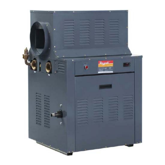
Raypak Commercial Power Vent
Installation and Operating Instructions
This Installation and Operating Instructions Manual is provided with the information for the installation,
operation and maintenance of your Raypak Heater. Please review and follow these procedures carefully.
Keep this manual in a safe and accessible place for easy reference in the future.
Water Heaters
Models
B0520
B0670
B0770
B0870
Advertisement
Table of Contents

Subscribe to Our Youtube Channel
Related Manuals for Raypak B0520


Summary of Contents for Raypak B0520
- Page 1 This Installation and Operating Instructions Manual is provided with the information for the installation, operation and maintenance of your Raypak Heater. Please review and follow these procedures carefully. Keep this manual in a safe and accessible place for easy reference in the future.
- Page 2 Notice to Victorian Customers from the Victorian Plumbing Industry Commission. This water heater must be installed by a licensed person as required by the Victorian Building Act 1993. Only a licensed person will give you a Compliance Certificate, showing that the work complies with all the relevant standards.
-
Page 3: Table Of Contents
TROUBLESHOOTING ........................37 SERVICING ............................ 38 RAYPAK COMMERCIAL WATER HEATER WARRANTY ............. 40 Upon completion of the installation and commissioning of the water heater, leave this guide with the householder or responsible officer. DO NOT leave this guide inside of the cover of the water heater, as it may interfere with the safe operation of the water heater or ignite when the water heater is turned on. -
Page 4: For Your Safety
FOR YOUR SAFETY WARNING For your safety do not operate this appliance before reading this instruction booklet Improper installation, adjustment, alteration, service or maintenance can cause injury or property damage. For assistance or additional information consult the Rheem Service Department or accredited Service Agent. WHAT TO DO IF YOU SMELL GAS? DO NOT try to light any gas appliance. -
Page 5: About The Water Heater
Modulating type suitable for indoor or outdoor installation. Raypak heaters utilise a finned copper tube heat exchanger resulting in a low water content and reduced ‘stand by’ heat losses. Therefore a circulator pump of sufficient capacity to match the water heater model must be installed in the system. -
Page 6: Water Supplies
The standard finned copper tube heat exchanger has proved to be very resilient and capable of operating for many trouble free years on most public water supplies. Should the installation be in an area where ‘corrosive’ or ‘hard’ water is present contact Raypak to ensure that the quality of the water is satisfactory. -
Page 7: Installation
INSTALLATION THIS WATER HEATER IS NOT SUITABLE FOR POOL HEATING. BEFORE COMMENCING THE INSTALLATION: 1. Read these instructions in full. 2. Check that the heater you have been supplied is suitable for the type of installation and the gas that is available. The gas supply pressure must be between the minimum and maximum as shown on the water heater rating plate. -
Page 8: Water Heater Location
INSTALLLATION IMPORTANT: When installing a new water heater to an existing system, it is a Raypak requirement that the system and its equipment be inspected, drained and flushed with clean fresh water, before the new water heater is connected. Failure to do this may cause blockages and/or water heater damage which is NOT COVERED BY WARRANTY. -
Page 9: Water Heater Dimensions
INSTALLLATION WATER HEATER DIMENSIONS Model 674mm 797mm 901mm 1006mm 821mm 944mm 1048mm 1153mm CLEARANCES – INDOOR INSTALLATIONS from combustible materials: from non-combustible materials: Rear 600mm 150mm Front (access) 750mm 750mm Flue Outlet Side* 700mm 700mm Left Side* 600mm 600mm Right Side* 600mm 300mm Top (access) -
Page 10: Flueing
The secondary flue connected to this water heater may discharge horizontally or vertically. • All indoor installations require a 250mm barometric damper to be installed in the connecter from each water heater. A barometric damper is available from Raypak. Horizontal Discharge •... - Page 11 If the flue cannot be designed as described above, then a power flue may be required. Power flues must be designed by persons competent to do so and must be interlocked with the water heater. Contact Raypak for power flue wiring diagrams.
-
Page 12: Gas Inlet
INSTALLLATION Flue Outlet Direction The flue connection on this water heater can be repositioned from the left hand side to the right hand side if required. • Ensure the water heater is isolated from the mains power supply. • Remove the 18 screws holding the fan cover assembly to the water heater body and the 6 screws around the flue connection. -
Page 13: Pump Selection
Pipe Size and Pump Selection Table Pump Minimum Manifold Header Size (mm) Branch Model Size Speed TP Series 1 Unit 2 Units 3 Units 4 Units Series B0520 32-80B 32mm B0670 32-80B 40mm 32-80B 50-30/4B 50mm B0770 40-60/2B 40mm 32-80B 2 ½... -
Page 14: Cold Water Supply / Make-Up
INSTALLLATION TP series circulator is recommended for hard water areas in lieu of UPS series circulator * Manifold header sizes are minimum requirements for water heater performance Minimum Pump Inlet Pressure Circulating pumps require a minimum inlet pressure in order to operate without cavitation. Refer to the table below for minimum pressure requirements for Grundfos UPS series pumps. -
Page 15: Plumbing Connections
INSTALLLATION The cold water supply pressure must be sufficient to provide adequate flow at the fixtures. EXPANSION CONTROL VALVE Local regulations may make it mandatory to install an expansion control valve (ECV) in the cold water line to the water heating system. In other areas, an ECV is not required unless the saturation index is greater than +0.4 (refer to 'Water Supplies' on page 6). - Page 16 INSTALLLATION...
- Page 17 INSTALLLATION Typical Installation one water heater one tank...
- Page 18 INSTALLLATION Typical Installation two water heaters, two tanks Mechanical, Hydronic and Process Heating Applications For these applications, storage tanks are normally not required. Connect the water heaters and pumps in accordance with the principles shown in the diagram below with the following in mind: •...
- Page 19 INSTALLLATION LEGEND Typical Installation - Raypak mechanical heating system CLOSED LOOP WATER SOURCE HEAT PUMP Refer to diagram below 1. Only use a heater with on/off controls. 2. The bypass pipe diameter MUST be the same as the inlet and outlet pipes.
-
Page 20: Electrical Supply
INSTALLLATION ELECTRICAL SUPPLY The electrical installation must comply with AS/NZS 3000 and any local requirements. This water heater must be hard wired to a 240V AC 50 Hz M.E.N. (multiple earthed neutral) mains power supply with an all pole isolating switch installed adjacent to and accessible from the water heater (refer to AS 5601, 5.2.11). - Page 21 INSTALLLATION the conduit and the water heater cabinet to prevent overheating of the wiring. The power for the pump and the water heater must be supplied from the same circuit and isolating switch; alternatively the water heater power supply may be switched by the auxiliary contacts of the pump contactor (refer to diagrams on page 22).
- Page 22 INSTALLLATION Wiring diagram Raypak water heater with 415V 3 phase circulator Wiring diagram Raypak Water Heater with 240V Single Phase Circulator...
- Page 23 (Installed INLET side of heater) FI L TER NOTE!: This Drawing May Change WIthout Notice This drawing remians the property of Raypak Australia and must not be reproduced without permission. Water Heater On/Off (INTERRUPTED PILOT) LME39 + RE3 + AKO...
- Page 24 BLUE speed is low (White) Standard (240V) NOTE!: This Drawing May Change WIthout Notice Medium speed (Gray) This drawing remians the property of Raypak Australia Run Relay High speed (Brown) and must not be reproduced without permission. Flame Fail Relay...
-
Page 25: Ambient Air Compensation
INSTALLLATION AMBIENT AIR COMPENSATION QAC22 / QAC32 Mounting and Installation Mounting Position Mounting instructions are printed on the packaging however the following points should be noted • The sensor is to be mounted externally, preferably at the mid point of the house or building or heating zone, but at least 2.5 m above the ground The sensor must not be fitted at the following locations:... -
Page 26: Commissioning
COMMISSIONING COMMISSIONING MUST ONLY BE UNDERTAKEN BY A PROPERLY QUALIFIED AND IN MOST CASES APPROPRIATELY LICENSED PERSON WHO IS FAMILIAR WITH THE COMMISSIONING REQUIREMENTS OF AS3814. MOST REGULATORY AUTHORITIES REQUIRE THE APPLIANCE AND ITS INSTALLATION TO BE INSPECTED AND CERTIFIED. PRE-COMMISSIONING CHECK LIST 1. - Page 27 COMMISSIONING CLOSED LOOP WATER SOURCE HEAT PUMP Commissioning procedure – refer to diagram below Check that both isolation valves are open. Adjust balancing valve A to half open and balancing valve B to fully open. Start up the heater and adjust balancing valve A to obtain a heater inlet temperature of approximately 10°C greater than the system loop return temperature, (turning valve A in the open direction will increase the heater inlet temperature and closing valve A will lower the heater inlet temperature.
-
Page 28: Operation
OPERATION FIRST FIRING OF WATER HEATER It is quite normal for the water heater to produce some smoke, fumes and possible condensation for the first thirty (30) minutes of firing from new. Avoid breathing fumes. Vacate and ventilate area. LIGHTING PROCEDURE CAUTION Do not use this heater if any part has been under water. -
Page 29: To Turn Off The Water Heater
OPERATION TO TURN OFF THE WATER HEATER 1. Turn off the power supply to the water heater at the isolation switch. EMERGENCY SHUT-DOWN 1. Turn off the power supply to the water heater at the isolation switch. 2. Turn off the gas isolation valve at the inlet to the water heater or the main gas supply. CHECK FOR NORMAL OPERATION •... -
Page 30: Adjustment
The thermostat has a number of parameters that are programmed during manufacture (refer to the ‘AKO Parameter table’ on page 31 for values); advice should be sort from your local Raypak representative prior to altering any values other than the set point or the differential. - Page 31 The thermostat has a number of parameters that are programmed during manufacture (refer to the ‘RWF40 Parameter Table’ on page 32 for values); advice should be sort from your local Raypak representative prior to altering any values other than the set point or the differentials.
- Page 32 ADJUSTMENT To adjust the Differential (HyS1 and HyS3) To adjust the differential it is necessary to enter the programming mode (refer to ‘To adjust parameters’ below). To adjust parameters 1. Press the ‘PGM’ button for 2 seconds, the display will show ‘AL’ 2.
-
Page 33: Burner Gas Pressure Adjustment
ADJUSTMENT BURNER GAS PRESSURE ADJUSTMENT On/Off Models The burner pressure is set by adjusting the Jeavons J48 appliance regulator. To adjust the burner pressure: 1. Fit manometer to main burner test point 2. Turn on electrical power to heater 3. Allow main burner to light 4. -
Page 34: Temperature Rise
ADJUSTMENT TEMPERATURE RISE The correct temperature rise across the water heater heat exchanger is the result of correct pump selection and speed, pipe sizing (refer to the section on 'Pump Selection' on page 13and good plumbing. The typical temperature rises for most applications will be between 10°C and 20°C. A temperature rise of less than 10°C is indicative of excessive flow rate that can lead to erosion of the tube bundle and/or headers. -
Page 35: Air Pressure Switch
ADJUSTMENT AIR PRESSURE SWITCH The air pressure switch is calibrated at the time of manufacture. The pressure switch contacts are adjusted to close when the pressure detected at the test point is 150Pa or greater. Depending on the installation it may be necessary to adjust the pressure switch setting. WARNING: Under no circumstances is the pressure switch to be adjusted to cause the contacts to close at a pressure less than 150Pa. -
Page 36: Fan Speed Adjustment
ADJUSTMENT FAN SPEED ADJUSTMENT The fan motor has 3 possible speeds, low, medium or high. The appliance is wired for low speed at the time of manufacture; depending on the installation it may be necessary to increase the fan speed. To alter the fan speed Isolate power to the water heater / pool heater Open the control panel... -
Page 37: Troubleshooting
TROUBLESHOOTING RESETTING THE WATER HEATER If the pilot OR main burner fail to light within a prescribed time the ignition system will enter a lockout condition, indicated by the illuminating of a RED light on the control panel. Turning the power off and then on again will not reset this condition. To reset the water heater: •... -
Page 38: Servicing
PERFORMED BY A SUITABLY LICENSED PERSON RECOMMENDED SERVICE PROCEDURES It is a requirement of Raypak and all gas authorities that the heater be serviced at least once per year. Where it is used in a specific application, e.g. mechanical heating, it would be practical to perform the service at the commencement of the heating season, or at any time there may be an indication of a problem. - Page 39 13. Clear and remove any dust and debris from the appliance and its immediate area. FIRE TILE (REFRACTORY) HANDLING CAUTION: Ceramic refractories are used in Raypak heaters. Please refer to the Material Safety Data Sheet (MSDS) provided for safe handling of this insulation.
-
Page 40: Raypak Commercial Water Heater Warranty
In addition to this warranty, the Trade Practices Act 1974 and similar laws in each state and territory provide the owner under certain circumstances with certain minimum statutory rights in relation to your Raypak water heater. This warranty must be read subject to that legislation and nothing in this warranty has the effect of excluding, restricting or modifying those rights. - Page 41 RHEEM SERVICE 131031 WWW.RHEEM.COM.AU Manufactured by Raypak Australia Ph (03) 9757 3333 Fax (03) 9757 4974 Part No. 209130.5: Effective 01/07/2007 (Replaces: 01/10/2000)
Need help?
Do you have a question about the B0520 and is the answer not in the manual?
Questions and answers