Sign In
Upload
Download
Table of Contents
Contents
Add to my manuals
Delete from my manuals
Share
URL of this page:
HTML Link:
Bookmark this page
Add
Manual will be automatically added to "My Manuals"
Print this page
×
Bookmark added
×
Added to my manuals
Manuals
Brands
Raypak Manuals
Water Heater
B0200
Owner's manual
Raypak B0200 Owner's Manual
Hide thumbs
1
2
Table Of Contents
3
4
5
6
7
8
9
10
11
12
13
14
15
16
17
18
19
20
21
22
23
24
25
26
27
28
29
30
31
32
33
34
35
36
37
38
39
40
page
of
40
Go
/
40
Contents
Table of Contents
Bookmarks
Table of Contents
Table of Contents
Contents
About Your Water Heater
How Your Water Heater Works
Save a Service Call
Regular Care
Installation
Connections - Plumbing
Connections - Electrical
Location of Controls
Safety Precautions
Commissioning
Operating the Water Heater
Temperature Control
Service Procedures
Water Supplies
Warranty
Advertisement
Quick Links
1
Table of Contents
2
About Your Water Heater
3
How Your Water Heater Works
4
Installation
5
Connections - Plumbing
6
Commissioning
7
Temperature Control
8
Service Procedures
Download this manual
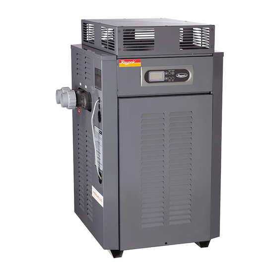
Owner's Guide
and
Installation Instructions
Raypak Water Heaters
Models
Types
B0200
B0280
NCO, NCM
B0350
PCO, PCM
B0430
This water heater must be installed and serviced by a qualified person.
Please leave this guide with a responsible officer.
Table of
Contents
Previous
Page
Next
Page
1
2
3
4
5
Advertisement
Table of Contents
Need help?
Do you have a question about the B0200 and is the answer not in the manual?
Ask a question
Questions and answers
Related Manuals for Raypak B0200
Water Heater Raypak B-195 Operating And Installation Instructions
Gas fired automatic instantaneous booster water heater (23 pages)
Water Heater Raypak B0109 Owner's Manual And Installation Instructions
Raypak water heater user manual (43 pages)
Water Heater Raypak B0147 Owner's Manual And Installation Instructions
Nco, nch pco, pch types (44 pages)
Water Heater raypak B0430 Owner's Manual
(40 pages)
Water Heater Raypak B0507 Owner's Manual And Installation Instructions
(57 pages)
Water Heater Raypak B0520 Installation And Operating Instructions Manual
Commercial power vent water heaters (41 pages)
Water Heater Raypak RSIT30 Installation & Operating Instructions Manual
Stainless steel indirect fired storage water heater (20 pages)
Water Heater Raypak 0133-4001 WH Installation And Operating Instructions Manual
Hot water supply heaters models 0133-4001 types wh & nh (53 pages)
Water Heater Raypak 1334001 Installation & Operating Instructions Manual
Raytherm hot water supply heaters type wh (52 pages)
Water Heater Raypak RAYTHERM 2100 Specifications
Commercial water heaters (2 pages)
Water Heater Raypak HI DELTA HD101 Installation & Operating Instructions Manual
H & wh series (48 pages)
Water Heater Raypak RayTherm Commercial Boilers And Water Heater Brochure & Specs
Commercial boilers and water heaters (4 pages)
Water Heater Raypak 122-322 Operating And Installation Instructions
Type h, wh, & p hi delta 122; 162; 202; 242; 322 (56 pages)
Water Heater Raypak MVB 503 Brochure & Specs
Modulating vertical boilers & water heaters (8 pages)
Water Heater Raypak Hot Water Supply LAUNDRY-PAK Specifications
Hot water supply for coin-operated and commercial laundries (2 pages)
Water Heater Raypak 2100 - 4001 Owner's Manual
Raytherm wh water heaters commercial (2 pages)
This manual is also suitable for:
B0280
B0430
B0350
Table of Contents
Print
Rename the bookmark
Delete bookmark?
Delete from my manuals?
Login
Sign In
OR
Sign in with Facebook
Sign in with Google
Upload manual
Upload from disk
Upload from URL


Need help?
Do you have a question about the B0200 and is the answer not in the manual?
Questions and answers