Table of Contents
Advertisement
Quick Links
Advertisement
Table of Contents

Subscribe to Our Youtube Channel
Summary of Contents for abaco systems RTM311
- Page 1 RTM311 User Manual Abaco Systems Support Portal This document is the property of Abaco Systems, Inc. and may not be copied nor communicated to a third party without the written permission of Abaco Systems, Inc. © Abaco Systems, 2017 UM082 www.abaco.com...
- Page 2 UM082 RTM311 User Manual r1.3 Revision History Document Changes Author Peer Quality Date Review Approval Revision r1.0 Initial Release Jpat 2017/09/25 Changed SW4’s default position to r1.1 Jpat 2017/10/20 “OFF” r1.2 Added USB3.0 and DisplayPort Jpat 2017/11/17 verification and BSP details Added remark about 1000BASE-T only on RJ45’s...
-
Page 3: Table Of Contents
UM082 RTM311 User Manual r1.3 1 Table of Contents Table of Contents ......................3 Acronyms ........................4 Terms used ........................4 Related Documents ......................4 General Description ....................... 5 Installation ........................6 Hardware Specifications ....................6 Physical specifications ....................6 7.1.1... -
Page 4: Acronyms
• On-board connectors: Any connectors (except the VPX connectors) on the RTM311 that cannot be accessed from the front panel. • On-board switches: Any switches on the RTM311 that cannot be accessed from the front panel. 4 Related Documents •... -
Page 5: General Description
5 General Description The RTM311 is a 3U VPX Rear Transition Module. It is intended to be used in combination with certain 4DSP’s Xilinx FPGA VPX boards, typically VP881. The board implements features that are required to bring several interfaces of a VPX board to the rear panel. Some of those interfaces are: USB2.0, USB3.0, DisplayPort, Gigabit Ethernet and SD card. -
Page 6: Installation
6 Installation Requirements and handling instructions • The RTM311 is not hot-pluggable and must be installed in a system that is switched off • The RTM311 must only be installed with an appropriate VPX board such as VP881 (Contact Abaco Systems for options) •... -
Page 7: Connectors Location
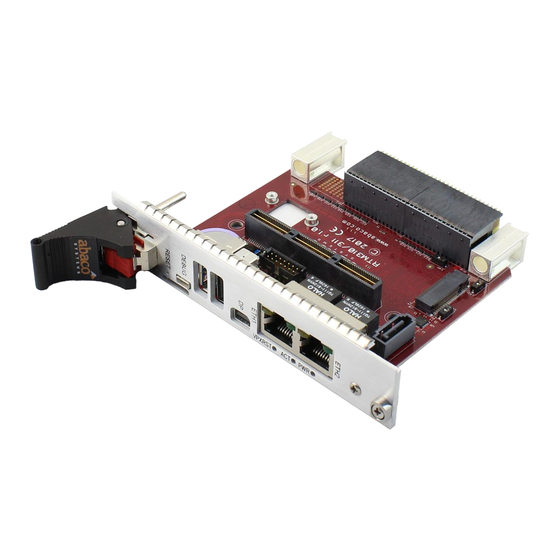
Connectors location 7.1.4.1 VPX connectors location The VPX connectors location on the RTM311 is shown in Figure 3 in section 7.1.4.3. 7.1.4.2 Front panel connectors location The location of connectors is shown in the picture below. Pins assignment is provided in section 7.2. -
Page 8: Esd Protection
UM082 RTM311 User Manual r1.3 Figure 3: RTM311 On-board Connectors locations ESD Protection The front panel connectors have ESD protection compliant to IEC 61000-4-2, ±15kV (air), ±8kV (contact). Switches On-board switches can be identified by the silkscreen. “RESET” button/momentary switch 7.3.1... -
Page 9: I2C Switch
UM082 RTM311 User Manual r1.3 7.3.3 I2C switch The I2C interface connects to I2C Master signals that come from the VPX connector pins: LOCAL-I2C_SCL: see section 7.5.1. LOCAL-I2C_SDA: see section 7.5.1. It’s called a LOCAL I2C interface, to differ from the SMBus interface on VPX RP0. -
Page 10: Leds
UM082 RTM311 User Manual r1.3 The VPX backplane’s I2C interface can be connected to the other RTM311’s I2C interfaces by writing to the I2C switch to connect its ports as below. I2C switch (PCA9548) port Description Port1 Connect VPX backplane to CPLD, DisplayPort Driver, SATA Re-driver Port2 Connect VPX backplane to MGT and legacy LVDS on QTE connector. -
Page 11: Connectors
UM082 RTM311 User Manual r1.3 Connectors The connectors pin assignment tables are broken down as per the VITA 46 connector nomenclature (RP0, RP1). The wafer positions are also provided. 7.5.1 VPX connectors 7.5.1.1 RP0 connector Position Wafer type Row G... - Page 12 UM082 RTM311 User Manual r1.3 Pin/Signal Description Connects to 12 Volt non-isolated Power Supply Tree 3.3 Volt non-isolated Power Supply Tree 5 Volt non-isolated Power Supply Tree Geographical Address Inputs GA [4:0]*, GAP* Connects to CPLD. 0-4, Parity Connects to 6-pin header (incl GND) and optionally...
- Page 13 UM082 RTM311 User Manual r1.3 7.5.1.2 RP1 connector RP1 has all positions loaded with differential wafers. A total of 32 differential pairs are available on RP1: Wafer Position type Row G Row F Row E Row D Row C Row B...
- Page 14 UM082 RTM311 User Manual r1.3 Pin/Signal Description Interface type Connects to USB2.0 OTG VBUS +5V power USB2.0_VBUS USB power switch voltage USB2.0_DP/DM USB2.0 OTG interface USB diff pair USB PHY Optional local reset 3.3V, open drain Place 4K7 pull-up to 3V3 and...
-
Page 15: Front Panel Connectors
The system can be debugged using a debug cable which is provided with RTM311. The debug cable is a customised break-out cable shown below. Each cable end has its own ID label. The “RTM31x Debug” end is to connect to RTM311 via its front panel’s µHDMI “Debug” connector. - Page 16 GPIO_DISC0, Reserved GPIO_I2C_SDA GPIO_I2C_SCL 7.5.2.3 USB2.0 connector RTM311 has a USB3.0 hub which accommodates the use of both the USB2.0 and USB3.0 interfaces. The USB2.0 interface is connected to VPX backplane per table below. USB2.0 connector VPX backplane signals Pin1, Vcc Pin2, DATA_N USB2.0_DM...
- Page 17 UM082 RTM311 User Manual r1.3 USB3.0 on RTM311 has not been completely verified because of limited support of this feature in the Xilinx PetaLinux BSP of the Zynq Ultrascale+ MPSoC device on the VP881. Contact Abaco sales for more information on the roll-out schedule of an updated Zynq MPSoC BSP for VP881 that fully supports USB3.0.
-
Page 18: On-Board Connectors
Figure 5: JTAG connector pinout 7.5.3.2 QTE connector (QTE-060-03-FL-D-A-TR) RTM311 provides access to VPX backplane’s differential signals via a QTE connectors. The signals assignment on the QTE connector is per the table below. Table 6: Signals assignment on the QTE connector... - Page 19 UM082 RTM311 User Manual r1.3 QTE connector pin VPX RP0 signal 25/27 FPGA-RX4+/ FPGA-RX4- 26/28 FPGA-TX4+/ FPGA-TX4- 31/33 FPGA-RX5+/ FPGA-RX5- 32/34 FPGA-TX5+/ FPGA-TX5- 37/39 FPGA-RX6+/ FPGA-RX6- 38/40 FPGA-TX6+/ FPGA-TX6- 41/43 FPGA-RX7+/ FPGA-RX7- 42/44 FPGA-TX7+/ FPGA-TX7- LOCAL-I2C_SDA (See note below) LOCAL-I2C_SCL (See note below)
- Page 20 UM082 RTM311 User Manual r1.3 QTE connector pin VPX RP0 signal 5/6/11/12/17/18/23/24/29/30/ 35/36/45/46/87/88/121/122/123/124/ 125/126/127/128/129/130/131/132 Other pins Reserved for future development The QTE connector has pins location shown in the figure below. Odd pins are located on the top row, starts from Pin1 on the left and ends with Pin119 on the right. Even pins are located on the bottom row, starts with Pin2 on the left and ends with Pin120 on the right.
- Page 21 The M.2 interface is configured to support SSD module in SATA mode. To utilize this interface, the SW3 must be set to “ON” position. To mount an M.2 module on RTM311: • Identify the top side of the M.2 module by observing the ground pads shown in Figure 8 and Figure 9.
- Page 22 VPX backplane connects to both standard SATA and M.2 devices as shown in Figure 11 below. Figure 11: Connections between VPX backplane and SATA/M.2 connectors RTM311 provides reference clock (100MHz) to the M.2 modules. VPX backplane can control/monitor the M.2 device via on-board CPLD as below. Also, see Appendix A: CPLD Register map for more details.
- Page 23 7.5.3.4 Standard SATA connector (Molex, 067800-5005) On-board SATA interface can be accessed by setting SW3 = “OFF”. Note that: there is no mounting hardware and SATA’s power connector provided on the RTM311 for SATA connection. The signals assignment on the SATA connector is as per table below.
- Page 24 UM082 RTM311 User Manual r1.3 7.5.3.5 SM bus header VPX backplane’s SM bus interface can be monitored using the on-board SM bus header (Molex, 53398-0671). See the signal assignment in the table below. SM bus header VPX backplane signal +3.3V_AUX UM082 www.abaco.com...
-
Page 25: Cpld
UM082 RTM311 User Manual r1.3 CPLD Status, control and interrupt signals are made accessible on the CPLD. The on-board (XC2C256- 7CPG132I) is also used to do the tasks below. Translating I2C access to PHY MDIO access. Level translating some DisplayPort signals. -
Page 26: Ordering Information
UM082 RTM311 User Manual r1.3 7.11 Ordering Information For ordering information, contact Abaco sales and refer to the Part Number and Compatibility document. UM082 www.abaco.com page 26 of 28... -
Page 27: Appendix A: Cpld Register Map
UM082 RTM311 User Manual r1.3 7.12 Appendix A: CPLD Register map Register Description 0x00 Version Register “0x01” initial release with basic functions Bit 7..0 0x01 Command Register 1 Bit 0 Clear the interrupt register Bit 1 Test the interrupt inputs... - Page 28 UM082 RTM311 User Manual r1.3 Register Description Bit 4 M.2 device activity Bit 5 Loss of data from standard SATA driver Bit 6 VPX backplane is connected (SYS_CON) Bit 7 Reserved UM082 www.abaco.com page 28 of 28...
Need help?
Do you have a question about the RTM311 and is the answer not in the manual?
Questions and answers