
Related Manuals for Daikin RZQ Series FCQ20EVA


Summary of Contents for Daikin RZQ Series FCQ20EVA
- Page 1 SiME281501E Service Manual RZQ Series Heat Pump R410A 60Hz RZQ20 / 24 / 36 / 45LVA RZQ45 / 48MYL...
-
Page 2: Table Of Contents
SiME281501E TopAir RZQ Series Heat Pump R410A 60Hz ED Reference For items below, please refer to Engineering Data. Item ED No. Page Remarks Specification EDTW281313A P. 9-22 Option List EDTW281313A P. 70-72 1. Introduction .................... iv 1.1 Safety Cautions ..................iv 1.2 Used Icons .................... - Page 3 SiME281501E 4. Function Details ..................27 4.1 Indoor Unit....................27 4.2 Outdoor Unit ...................32 Part 5 Field Setting ..............48 1. Test Operation ..................49 1.1 Check Items before the Test Operation ..........49 1.2 Test Operation..................49 2. Field Setting from Remote Controller............51 2.1 Wired Remote Controller................51 2.2 Wireless Remote Controller ..............52 2.3 Setting Contents and Code No.
- Page 4 SiME281501E 4.12 Transmission Error between Indoor Unit PCB and Fan PCB....101 4.13 Thermistor Abnormality ................103 4.14 Combination Error between Indoor Unit PCB and Fan PCB ....104 4.15 Humidity Sensor System Abnormality ..........105 4.16 Room Temperature Thermistor in Remote Controller Abnormality ..106 4.17 Outdoor Unit PCB Abnormality.............107 4.18 High Pressure Abnormality (Detected by the High Pressure Switch)...108 4.19 Low Pressure Abnormality ..............110...
-
Page 5: Introduction
SiME281501E Introduction 1. Introduction Safety Cautions Be sure to read the following safety cautions before conducting repair work. Cautions and The caution items are classified into “ Warnings Warning” and “ Caution”. The “ Warning” items are especially important since they can lead to death or serious injury if they are not followed closely. - Page 6 Introduction SiME281501E Warning Be sure to wear a safety helmet, gloves, and a safety belt when working at a high place (more than 2 m). Insufficient safety measures may cause a fall accident. In case of R410A refrigerant models, be sure to use pipes, flare nuts and tools for the exclusive use of the R410A refrigerant.
- Page 7 SiME281501E Introduction 1.1.2 Cautions Regarding Safety of Users Warning Be sure to use parts listed in the service parts list of the applicable model and appropriate tools to conduct repair work. Never attempt to modify the equipment. The use of inappropriate parts or tools may cause an electrical shock, excessive heat generation or fire.
- Page 8 Introduction SiME281501E Warning Check to make sure that the power cable plug is not dirty or loose, then insert the plug into a power outlet securely. If the plug has dust or loose connection, it may cause an electrical shock or fire. Be sure to install the product correctly by using the provided standard For unitary type installation frame.
-
Page 9: Used Icons
SiME281501E Introduction Caution Be sure to measure the insulation resistance after the repair, and make sure that the resistance is 1 M or higher. Defective insulation may cause an electrical shock. Be sure to check the drainage of the indoor unit after the repair. Defective drainage may cause the water to enter the room and wet the furniture and floor. -
Page 10: Part 1 General Information
SiME281501E Part 1 General Information 1. Model Name of Indoor / Outdoor Units ...........2 2. External Appearance................3 General Information... -
Page 11: Model Name Of Indoor / Outdoor Units
SiME281501E Model Name of Indoor / Outdoor Units 1. Model Name of Indoor / Outdoor Units Model series Indoor unit Outdoor unit Power supply intake FCQ20EVA RZQ20LVA FCQ24EVA RZQ24LVA Outdoor unit: 1 phase, 220V, 60Hz FCQ36EVA RZQ36LVA Ceiling Mounted FCQ45EVA RZQ45LVA Cassette Type FCQ36EVA... -
Page 12: External Appearance
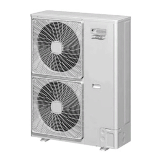
External Appearance SiME281501E 2. External Appearance Indoor unit FBQ-DA Wired remote controller BRC1C61 BRC1D61 Wireless remote controller BRC7F632F (for FCQ) Signal receiver unit Signal receiver unit BRC4C62 (for FBQ-DA) (for FCQ) (for FBQ-DA) Outdoor unit RZQ20LVA RZQ36LVA RZQ24LVA RZQ45LVA RZQ45MYL RZQ48MYL General Information... -
Page 13: Part 2 Functions
SiME281501E Part 2 Functions 1. Functions....................5 Functions... -
Page 14: Functions
Functions SiME281501E 1. Functions Indoor FCQ20-45EVA FBQ20-48EVA unit Items Features Outdoor RZQ20-45LVA RZQ20-45LVA unit RZQ45-48MYL RZQ45-48MYL Comfort Auto swing — Swing pattern selection — Draft prevention function (heating) — (2 step) (2 step) Switchable fan speed Auto airflow rate —... -
Page 15: Part 3 Remote Controller
SiME281501E Part 3 Remote Controller 1. Wired Remote Controller.................7 1.1 Applicable Models ..................7 1.2 Names and Functions ................8 1.3 MAIN/SUB Setting when Using 2 Remote Controllers ......11 1.4 Centralized Control Group No. Setting...........12 2. Wireless Remote Controller ..............13 2.1 Applicable Models ..................13 2.2 Names and Functions ................13 2.3 Address and MAIN/SUB Setting.............15 3. -
Page 16: Wired Remote Controller
Wired Remote Controller SiME281501E 1. Wired Remote Controller Applicable Models Model Series FCQ-EV FBQ-EV Remote Controller Heat Pump BRC1C61 Wired Remote Controller with Weekly BRC1D61 Schedule Timer Remote Controller... -
Page 17: Names And Functions
SiME281501E Wired Remote Controller Names and Functions 1.2.1 BRC1C61 ON/OFF BUTTON DISPLAY “ ” (DEFROST) Press the button and the system will start. Press the button again and the system will stop. NON-FUNCTIONING DISPLAY OPERATION LAMP (RED) If that particular function is not available, pressing The lamp lights up during operation. - Page 18 Wired Remote Controller SiME281501E 1.2.2 BRC1D61 ON/OFF BUTTON EXTERNAL CONTROL ICON Press the ON/OFF button to start or stop the system. This icon indicates that another controller with higher priority is controlling or disabling your installation. OPERATION LAMP CHANGE-OVER UNDER CENTRALIZED The operation lamp lights up during operation or CONTROL ICON blinks if an error occurs.
- Page 19 SiME281501E Wired Remote Controller 1 2 3 4 5 SCHEDULE TIMER BUTTON ACTION ICONS These icons indicate the actions for each day of the This button enables or disables the schedule timer. schedule timer. TIME ADJUST BUTTON OFF ICON These buttons are used to adjust the clock or, when in This icon indicates that the OFF action is selected programming mode, to adjust the programmed action when programming the schedule timer.
-
Page 20: Main/Sub Setting When Using 2 Remote Controllers
Wired Remote Controller SiME281501E MAIN/SUB Setting when Using 2 Remote Controllers Situation The MAIN/SUB setting is necessary when 1 indoor unit is controlled by 2 remote controllers. When you use 2 remote controllers (control panel and separate remote controller), set one to MAIN and the other to SUB. Setting The remote controllers are set at factory to MAIN, so you only have to change 1 remote controller from MAIN to SUB. -
Page 21: Centralized Control Group No. Setting
SiME281501E Wired Remote Controller Centralized Control Group No. Setting 1.4.1 BRC1C61/BRC1D61 In order to conduct the centralized remote control using the central remote controller and the unified ON/OFF controller, Group No. settings should be made by group using the operating remote controller. Make Group No. -
Page 22: Wireless Remote Controller
Wireless Remote Controller SiME281501E 2. Wireless Remote Controller Applicable Models Model Series FBQ-DA Remote Controller Heat Pump BRC7F632F BRC4C62 Names and Functions 3P107422-11J Receiver FCQ-K/KA FBQ-DA (separate type) 3P107422-21S 3P107422-11J Remote Controller... - Page 23 SiME281501E Wireless Remote Controller AIRFLOW DIRECTION ADJUST BUTTON DISPLAY “ ” (SIGNAL OPERATION MODE SELECTOR BUTTON TRANSMISSION) Press this button to select OPERATION This lights up when a signal is being MODE. transmitted. FILTER SIGN RESET BUTTON DISPLAY “ ” “ ”...
-
Page 24: Address And Main/Sub Setting
Wireless Remote Controller SiME281501E Address and MAIN/SUB Setting Introduction To set the wireless remote controller, you have to set the address for: The receiver of the wireless remote controller The wireless remote controller. Setting the Address for the Receiver The address for the receiver of the wireless remote controller is factory setting to 1. - Page 25 SiME281501E Wireless Remote Controller Multiple Settings A/b When the indoor unit is being operating by external control (central remote controller, etc.), it sometimes does not respond to ON/OFF and temperature setting commands from this remote controller. Check what setting the customer wants and make the multiple setting as shown below. Remote controller Multiple Remote controller...
-
Page 26: Service Mode
Service Mode SiME281501E 3. Service Mode BRC1C61/BRC1D61 3.1.1 Display Service Data Unit No. Mode No. Second Field Code No. Setting Mode First Code No. 1. Enter the field setting mode. Press the INSPECTION/TEST button for 4 seconds or more. 2. Enter the service mode. After having entered the field setting mode, press the INSPECTION/TEST button for 4 seconds or more. - Page 27 SiME281501E Service Mode 3.1.2 Service Setting Mode No. Unit No. Mode No. Field Setting Mode Second Field Code No. Setting Mode First Code No. Second Code No. First Code No. 1, 2, 6 1. Enter the field setting mode. Press the INSPECTION/TEST operation button for 4 seconds or more. 2.
-
Page 28: Part 4 Function And Control
SiME281501E Part 4 Function and Control 1. Functions of Main Components and Thermistors .........20 2. Function Outline ..................23 2.1 Indoor Unit....................23 3. Operation Flow Chart ................25 3.1 Cooling / Dry Operation................25 3.2 Heating Operation ..................26 4. Function Details ..................27 4.1 Indoor Unit....................27 4.2 Outdoor Unit ...................32 Function and Control... -
Page 29: Functions Of Main Components And Thermistors
SiME281501E Functions of Main Components and Thermistors 1. Functions of Main Components and Thermistors FCQ20EVA / FBQ20EVA + RZQ20LVA FCQ24EVA / FBQ24EVA + RZQ24LVA Function and Control... - Page 30 Functions of Main Components and Thermistors SiME281501E FCQ36EVA / FBQ36EVA + RZQ36LVA FCQ45EVA / FBQ45EVA + RZQ45LVA FCQ45EVA / FBQ45EVA + RZQ45MYL FCQ48EVA / RBQ48EVA + RZQ48MYL Function and Control...
- Page 31 SiME281501E Functions of Main Components and Thermistors Outdoor Unit (A) Compressor Inverter drive unit varies compressor operating frequency to control capacity and other factors. (B) Electronic Expansion Valve Provides control to maintain optimum operating condition for high efficiency. (C) Four Way Valve (Y1S) Changes operation of cooling / heating.
-
Page 32: Function Outline
Function Outline SiME281501E 2. Function Outline Indoor Unit (Input) (Output) Indoor Unit (Function) Suction Air Thermistor Thermostat Control Fan Motor Heat Exchanger Thermistor Monitoring Function Drain Pump Float Switch Program Dry Flap Motor Limit Switch for Flap Fan Operation LED Display Drain Pump Control Emergency Operation Switch Buzzer, LED... - Page 33 SiME281501E Function Outline (Input) (Output) Indoor Unit (Function) Suction Air Thermistor Thermostat Control Fan Motor LED Display Heat Exchanger Thermistor Monitoring Function Remote Controller with Liquid Program Dry Crystal Fan Operation Freeze-up Prevention Function Operation Mode Guard Function Filter Sign Function Error Detection Function Function and Control...
-
Page 34: Operation Flow Chart
Operation Flow Chart SiME281501E 3. Operation Flow Chart Cooling / Dry Operation Power supply ON Initialize electronic expansion valve Initialize micro-computer Stopping ∗1 Crankcase heater control ∗2 Preheating operation control Remote controller operation judgement Cooling / Dry Emergency Operation mode judgement Heating Emergency... -
Page 35: Heating Operation
SiME281501E Operation Flow Chart Heating Operation Power supply ON Initialize electronic expansion valve Initialize micro-computer Stopping ∗1 Crankcase heater control ∗2 Preheating operation control Remote controller ON operation judgement Cooling / Dry Emergency Operation mode judgement Heating Cooling / Dry Emergency Heating operation... -
Page 36: Function Details
Function Details SiME281501E 4. Function Details Indoor Unit 4.1.1 Thermostat Control Initial setting Set temperature –2 –1 0 +1 +2 Cooling thermostat ON Cooling thermostat OFF Heating thermostat OFF Heating thermostat ON 4.1.2 Draft Avoidance Control 1 (FCQ) Draft is circumvented by delaying transfer of the flap to the Po0 (horizontal) position for a certain amount of time when defrosting and in the heating mode with the thermostat OFF. - Page 37 SiME281501E Function Details 4.1.3 Draft Avoidance Control 2 (FCQ) When hot start is canceled or when cold air prevention control is finished, if the fan speed is set to “H,” the fan turns at L speed for a certain amount of time, thus avoiding draft while the flap is moving. OFF or LL Setting Flap...
- Page 38 Function Details SiME281501E 4.1.6 Drain Pump Control (FCQ) Cooling, Program Dry Normally drain pump ON (Thermostat is both ON or OFF) Heating When the following conditions are satisfied, the drain pump turns ON. Drain Pump 5 min. 5 sec. Float Switch Time...
- Page 39 SiME281501E Function Details Heating Set temperature (˚C) Suction air Suction air Room temperature Room temperature thermistor thermistor Suction air thermistor Suction air thermistor thermistor thermistor Suction air Suction air Room temperature Room temperature thermistor thermistor thermistor thermistor Suction air thermistor Suction air thermistor Suction air temperature (˚C) 4.1.8 Program Dry Operation Function...
- Page 40 Function Details SiME281501E 4.1.9 Automatic Restart Purpose The purpose of the auto-restart function is to automatically resume the same operating mode as when the unit was operating when the power supply is restored after a power failure. Do not use the "Automatic Restart" function to daily start/stop the unit. Precautions when turning OFF power ...
-
Page 41: Outdoor Unit
SiME281501E Function Details Outdoor Unit 4.2.1 Abnormal Stop (Retry Control) When the following items show abnormal values, the thermostat turns OFF and error is determined based on the number of retry in order to protect the compressor and other devices. Item Criteria Number of retry... - Page 42 Function Details SiME281501E 4.2.3 Crankcase Heater Control (Except RZQ50/60/71KCVLT) After the compressor has been turned OFF, the crankcase heater control will be activated in order to avoid refrigerant from dissolving in the compressor oil. 70˚C 75˚C Discharge pipe temperature [Ending Condition] •...
- Page 43 SiME281501E Function Details 4.2.5 Starting Control Starting Control When compressor start up, the starting frequency is fixed for specified period of time at low frequency to prevent returning of refrigerant. Ta: Outdoor air temperature Starting Pressure Pressure equalizing control equalizing complete complete start...
- Page 44 Function Details SiME281501E 4.2.6 Frequency Step Control Compressor operation frequency is controlled with the following steps in order to make evaporating temperature constant when cooling and make condensing temperature constant when heating. The target temperature of evaporation (Tes) in cooling varies within the range of 2°C Tes 20°C in accordance with Trs and indoor air conditioning load.
- Page 45 SiME281501E Function Details 4.2.7 General Electronic Expansion Valve Control When cooling/heating, PI control of electronic expansion valve is conducted to keep heat exchanger outlet subcooled degree constant in order to utilize outdoor unit heat exchanger fully. SH = R4T - Te SH: Heat exchanger outlet subcooled degree R4T: Suction pipe temperature (°C) Te: Low pressure equivalent saturation temperature (°C)
- Page 46 Function Details SiME281501E 4.2.10 Low Pressure Protection Control In order to prevent abnormal low pressures in the system, the below control function will be activated. Low pressure is detected by the low pressure sensor. RZQ20/24LVA (When cooling operation) (When heating operation) Normal operation Normal operation Lp >...
- Page 47 SiME281501E Function Details RZQ36/45LVA, RZQ45/48MYL (When cooling operation) (When heating operation) • Within 10 minutes after defrosting • Lp < 0.1 MPa continuous for 5 minutes & • Lp < 0.05 MPa Normal operation Normal operation • Within 5 minutes after Lp >...
- Page 48 Function Details SiME281501E Parameters RZQ36/45LVA, RZQ20/24LVA RZQ45/48MYL A Hz 118.5 Hz 62 Hz B Hz 93 Hz 62 Hz C MPa 3.22 MPa 3.68 MPa D MPa 3.32 MPa 3.77 MPa E MPa 3.92 MPa 3.92 MPa F MPa 3.18 MPa 3.63 MPa G MPa 2.94 MPa...
- Page 49 SiME281501E Function Details 4.2.13 Discharge Pipe Temperature Control The compressor operating frequency will be controlled in order to avoid abnormal high compressor temperatures (see also electronic expansion valve control). Normal operation • Td < A°C • Upper limit frequency Td > B°C •...
- Page 50 Function Details SiME281501E 4.2.14 Inverter Protection by Radiation Fin Temperature Restricts compressor operation upper limit frequency to prevent compressor from tripping due to radiation fin temperature. Radiation fin temperature ≥ A˚C Normal operation Compressor frequency –1 step/6 sec. Compressor frequency +1 step/2 min.
- Page 51 SiME281501E Function Details 4.2.17 Forced Thermostat OFF Thermostat OFF due to Freeze-up Prevention (Only in Cooling) Conducts thermostat OFF under the following temperature and period of time to prevent the indoor unit heat exchanger from freezing up. Indoor unit heat exchange temperature < –5˚C for 1 continuous minute &...
- Page 52 Function Details SiME281501E Heating Overload Control In heating overload condition, controls outdoor unit fan to secure the differential pressure between high and low pressures of compressor. Hp - Lp < 0.69MPa Hp < 2.94MPa & Outdoor unit fan = 8 step Hp - Lp >...
- Page 53 SiME281501E Function Details 4.2.21 Pump Down Residual Operation Conducts pump down residual operation when compressor stops to collect refrigerant in evaporator for preventing liquid refrigerant from remaining in the evaporator. Contents of Control Compressor 110 Hz 0 pls Electronic expansion valve (fixed opening degree) Solenoid valve for receiver gas purging (SVG) ON (open)
- Page 54 Function Details SiME281501E 4.2.23 Defrost Operation Outline When the unit is operating in heating mode, a defrost operation will be conducted in order to avoid ice formation on the outdoor unit heat exchanger. Defrost Starting Conditions Defrost will start when the following conditions have been realized: •...
- Page 55 SiME281501E Function Details Defrost control Defrosting start Defrosting complete previous control 155Hz Compressor Four way valve 150 pls A pls Electronic (wet protection control) expansion valve 0 pls (5~60 sec.) 0 pls (5 sec.) Outdoor unit fan Indoor unit fan A pls RZQ20/24LVA 480 pls...
- Page 56 Function Details SiME281501E 4.2.25 Simulated Operation Function RZQ20/24LVA When an error on one of the below thermistors occurs, operation will continue while displaying the applicable alarm on the remote controller. Radiation fin thermistor error is only displayed when pressing the INSPECTION/TEST button on the remote controller.
-
Page 57: Part 5 Field Setting
SiME281501E Part 5 Field Setting 1. Test Operation ..................49 1.1 Check Items before the Test Operation ..........49 1.2 Test Operation..................49 2. Field Setting from Remote Controller............51 2.1 Wired Remote Controller................51 2.2 Wireless Remote Controller ..............52 2.3 Setting Contents and Code No. for Indoor Units ........53 2.4 Setting Contents and Code No. -
Page 58: Test Operation
Test Operation SiME281501E 1. Test Operation Check Items before the Test Operation Item to check Is all wiring laid as instructed? Is all the wiring connected? Are there no missing or reversed phases? Is the wiring between units all in the correct order between the units? Power supply wiring Is the unit completely grounded? Transmission wiring... - Page 59 SiME281501E Test Operation 5. Press INSPECTION/TEST button and operate normally. 6. Confirm function of unit according to the operation manual. 7. If the decoration panel on the indoor unit has not been installed, turn OFF the power after the test operation.
-
Page 60: Field Setting From Remote Controller
Field Setting from Remote Controller SiME281501E 2. Field Setting from Remote Controller Individual function of indoor unit can be changed from the remote controller. At the time of installation or after service inspection / repair, make the field setting in accordance with the following description. Wrong setting may cause error. -
Page 61: Wireless Remote Controller
SiME281501E Field Setting from Remote Controller Wireless Remote Controller UP button Mode No. Field setting mode DOWN button RESERVE button First code No. MODE button Second code No. INSPECTION/TEST button Setting To set the field settings, you have to change: ... -
Page 62: Setting Contents And Code No. For Indoor Units
Field Setting from Remote Controller SiME281501E Setting Contents and Code No. for Indoor Units : Factory settings Second Code No. Mode First Description of the setting Code No. 10 (20) Filter Ultra Light Approx. Heavy Approx. — — contamination long life 10,000 5,000 heavy/light (Setting... - Page 63 SiME281501E Field Setting from Remote Controller 2.3.1 Detailed Explanation of Setting Modes Filter Sign Setting If switching the filter sign ON time, set as given in the table below. First Code Second Ultra Long Life Mode No. Standard Filter Long Life Filter Setting Code No.
- Page 64 Field Setting from Remote Controller SiME281501E Fan Speed Changeover when Heating Thermostat is OFF By setting to “Set Fan Speed,” you can switch the fan speed to the set fan speed when the heating thermostat is OFF. Since there is concern about draft if using “fan speed up when thermostat is OFF,” you should take the setup location into consideration.
- Page 65 SiME281501E Field Setting from Remote Controller Airflow Direction Setting Set the airflow direction of indoor units as given in the table below. (Set when optional air outlet blocking pad has been installed.) The second code No. is factory set to “01.” Setting Table Mode No.
-
Page 66: Setting Contents And Code No. For Outdoor Units
Field Setting from Remote Controller SiME281501E Setting Contents and Code No. for Outdoor Units Remote controller settings The table below contains the remote controller settings. : Factory setting Mode First Description of the Second Code No. Code setting 16 (26) Low night noise Disable Low night... - Page 67 SiME281501E Field Setting from Remote Controller 2.4.1 Low Night Noise Operation Purpose Lower the operation sound of the outdoor unit. Setting Silent Operation can be activated by: 1. Automatic control (By field setting from remote controller) 2. External activation (from optional PCB KRP58M51) ...
- Page 68 Field Setting from Remote Controller SiME281501E External Activation from Optional PCB Graph Low night noise operation can also be activated from the optional PCB (KRP58M51). Transmission connector (on outdoor unit PCB X6A) Power supply connector (on outdoor unit PCB X77A) 1 2 3 4 X800M X801M...
-
Page 69: Field Setting From Outdoor Unit Pcb
SiME281501E Field Setting from Outdoor Unit PCB 3. Field Setting from Outdoor Unit PCB Location of DIP Switch and BS Button Various settings are available by using the DIP switches and the BS buttons on the PCB (Display PCB: A2P). Display Lamp Display PCB (A2P) -
Page 70: Field Setting For Outdoor Unit
Field Setting from Outdoor Unit PCB SiME281501E Field Setting for Outdoor Unit 3.2.1 Setting by BS buttons With "Setting mode 1," "Setting mode 2" and "Monitor mode," various settings and data can be checked. (1) Setting mode 1 The initial status (normal operation) is "Setting mode 1." This mode indicates operating status. "TEST (test operation),"... - Page 71 SiME281501E Field Setting from Outdoor Unit PCB 3.2.3 Setting Mode 2 Outline In this mode, settings for the following items can be made by using BS buttons. Press and hold the MODE (BS1) button for 5 seconds and set to “Setting mode <Selection of setting conditions>...
- Page 72 Field Setting from Outdoor Unit PCB SiME281501E Setting of Refrigerant Recovery Mode When a refrigerant recovery unit is connected onsite to recover refrigerant, fully open the electronic expansion valve of the outdoor unit to help the recovery. [Work procedure] (1) Stop operation. (2) Turn ON refrigerant recovery mode by performing the following steps.
- Page 73 SiME281501E Field Setting from Outdoor Unit PCB 3.2.4 Monitor Mode In this mode, the following items can be checked by using the BS buttons. LED display To enter the monitor mode, press the MODE (BS1) button when in “Setting Setting item Data display mode 1”.
- Page 74 Field Setting from Outdoor Unit PCB SiME281501E 3.2.5 List of Contents of Retry and Error Take the following steps to check contents of retry and error. To enter "Monitor mode," press the MODE (BS1) <Display of RETURN 2> button when in "Setting mode 1." When SET (BS2) button is pressed, the LED display for RETURN 2 turns ON.
- Page 75 SiME281501E Field Setting from Outdoor Unit PCB k: ON h: OFF l: BLINK Error Contents of retry or error code l l h k l h h h l l k h h h h l l l k k h h h h Open phase or power supply voltage imbalance l l k h h l h h l l k k h h h h...
-
Page 76: Emergency Operation
Emergency Operation SiME281501E 4. Emergency Operation Forced Operation Emergency Operation of Indoor Units You can operate the system manually by changing the setting of the emergency switch (SS1) on the indoor unit’s PCB from “Normal” to “Emergency.” When switched however the equipment cannot regulate temperature. -
Page 77: Emergency Operation When The Remote Controller Is Lost
SiME281501E Emergency Operation Emergency Operation when the Remote Controller is Lost When the remote controller does not work due to battery failure or is lost, use this switch which is located beside the discharge grille on the master unit. When the remote controller does not work, but the battery low indicator on it is not lit, contact your dealer. -
Page 78: Part 6 Service Diagnosis
SiME281501E Part 6 Service Diagnosis 1. Maintenance Inspection ................71 1.1 Overview ....................71 2. Symptom-based Troubleshooting ............74 2.1 Overview ....................74 2.2 Equipment does not Operate ..............75 2.3 Indoor Unit Fan Operates, but Compressor does not Operate ....76 2.4 Cooling / Heating Operation Starts but Stops Immediately ....77 2.5 After Unit Shuts Down, It cannot be Restarted for a While ....78 2.6 Equipment Operates but does not Provide Cooling .......80 2.7 Equipment Operates but does not Provide Heating .......81... - Page 79 SiME281501E 4.28 Radiation Fin Temperature Rise ............126 4.29 DC Output Overcurrent ................128 4.30 Electronic Thermal (Time Lag) .............130 4.31 Stall Prevention (Time Lag)..............132 4.32 Transmission Error between Control and Inverter PCB .......134 4.33 Transmission Error between Control and Inverter PCB .......135 4.34 Open Phase or Power Supply Voltage Imbalance .......137 4.35 Radiation Fin Thermistor (R10T) or Related Abnormality ....138 4.36 Defective Capacity Setting ..............139...
-
Page 80: Maintenance Inspection
Maintenance Inspection SiME281501E 1. Maintenance Inspection Overview When performing maintenance, you should at least perform the following inspections: Drain pumping out device (built-in) Model name (model name plate) Condensate removed from the room (Inside of suction grille) during cooling. ∗If the natural evaporative humidifier (option) is installed, it works also during the heating operation. - Page 81 SiME281501E Maintenance Inspection Guide Lines for Optimal Operation Condition The operation value guide lines when operating under standard conditions by pressing the INSPECTION/ TEST operation button on the remote controller are as given in the table below. Indoor unit fan: H tap High Discharge Suction Air...
- Page 82 Maintenance Inspection SiME281501E Correlation of Air Conditioner’s Operation Status and Pressure / Running Current What happens in comparison to normal values is summarized in the table below. (Measured for 15 ~ 20 minutes or more after operation starts.) Cooling Air Conditioner Status Low Pressure High Pressure Running Current...
-
Page 83: Symptom-Based Troubleshooting
SiME281501E Symptom-based Troubleshooting 2. Symptom-based Troubleshooting Overview Symptom Details of Measures Equipment does not operate. Refer to P.75 Indoor unit fan operates, but compressor does Refer to P.76 not operate. Cooling/heating operation starts but stops Refer to P.77 immediately. After unit shuts down, it cannot be restarted for a Refer to P.78 while. -
Page 84: Equipment Does Not Operate
Symptom-based Troubleshooting SiME281501E Equipment does not Operate Applicable Model All models of TopAir series Fuse blown or disorder of contact in operation circuit Supposed Defective operation switch or contact point Causes Defective high pressure switch Defective magnetic switch for fan motor ... -
Page 85: Indoor Unit Fan Operates, But Compressor Does Not Operate
SiME281501E Symptom-based Troubleshooting Indoor Unit Fan Operates, but Compressor does not Operate Applicable Model All models of TopAir series Fuse blown or disorder of contact in operation circuit Supposed Defective thermistor Causes Defective indoor/outdoor unit PCB Defective magnetic switch ... -
Page 86: Cooling / Heating Operation Starts But Stops Immediately
Symptom-based Troubleshooting SiME281501E Cooling / Heating Operation Starts but Stops Immediately Applicable Model All models of TopAir series Overcharge of refrigerant Supposed Air mixed in refrigerant system Causes Defective pressure switch Defective magnetic switch for outdoor unit fan motor ... -
Page 87: After Unit Shuts Down, It Cannot Be Restarted For A While
SiME281501E Symptom-based Troubleshooting After Unit Shuts Down, It cannot be Restarted for a While Applicable Model All models of TopAir series Overcurrent relay (for compressor) Supposed Causes Overcurrent relay may act due to the following reasons • Lower voltage of power supply •... - Page 88 Symptom-based Troubleshooting SiME281501E Troubleshooting Caution Be sure to turn off the power switch before connecting or disconnecting connectors, or parts may be damaged. Turn the operation switch ON and OFF, then wait at ON side. Does the Normal. Unit is in 3 minutes unit start operation after 3 minutes? standby mode.
-
Page 89: Equipment Operates But Does Not Provide Cooling
SiME281501E Symptom-based Troubleshooting Equipment Operates but does not Provide Cooling Applicable All models of TopAir series Models Wrong selection of model Supposed Refrigerant shortage Causes Insufficient airflow in the indoor unit Increase of high pressure In addition, the following errors may be conceivable •... -
Page 90: Equipment Operates But Does Not Provide Heating
Symptom-based Troubleshooting SiME281501E Equipment Operates but does not Provide Heating Applicable All models of TopAir series Models Wrong selection of model Supposed Refrigerant shortage Causes Insufficient airflow in the indoor unit Decrease of low pressure In addition, the following errors may be conceivable •... -
Page 91: Equipment Discharges White Mist
SiME281501E Symptom-based Troubleshooting Equipment Discharges White Mist Applicable Model All models of TopAir series Humid installation site Supposed Installation site is dirty and with dense oil mists Causes Soiled heat exchanger Clogged air filter Defective fan motor Troubleshooting Caution Be sure to turn off the power switch before connecting or disconnecting connectors, or parts may be damaged. -
Page 92: Equipment Produces Loud Noise Or Vibration
Symptom-based Troubleshooting SiME281501E Equipment Produces Loud Noise or Vibration Applicable All models of TopAir series Models Improper installation Supposed Contacts of fan, piping, casing, etc. Causes Noise of refrigerant flow Operating noise of drain discharge equipment ... -
Page 93: Equipment Discharges Dust
SiME281501E Symptom-based Troubleshooting 2.10 Equipment Discharges Dust Applicable Model All models of TopAir series Carpet Supposed Animal hair Causes Application (cloth shop,...) Troubleshooting Caution Be sure to turn off the power switch before connecting or disconnecting connectors, or parts may be damaged. Does the trouble generate at the time of operation start... -
Page 94: Troubleshooting By Led Indications
Troubleshooting by LED Indications SiME281501E 3. Troubleshooting by LED Indications Troubleshooting by LED on the Indoor Unit Foreword Troubleshooting can be carried out by service monitor LED (green). (Blinks when normal) k: LED ON / h: LED OFF / l: LED blinks Micro computer Normal Monitor Contents/Processing... -
Page 95: Troubleshooting By Remote Controller
SiME281501E Troubleshooting by Remote Controller 4. Troubleshooting by Remote Controller Procedure of Self-diagnosis by Remote Controller 4.1.1 Wired Remote Controller — BRC1C61/BRC1D61 If operation stops due to error, the remote controller’s operation LED blinks, and error code is displayed. (Even if stop operation is carried out, error contents are displayed when the inspection mode is entered.) The error code enables you to tell what kind of error caused operation to stop. - Page 96 Troubleshooting by Remote Controller SiME281501E 4.1.2 Wireless Remote Controller If unit stops due to an error, the operation indicating LED on the signal receiving part of indoor unit blinks. The error code can be determined by following the procedure described below. (The error code is displayed when an operation error has occurred.
- Page 97 SiME281501E Troubleshooting by Remote Controller Normal status Enters inspection mode from normal status when the INSPECTION/TEST button is pressed. 1 Press INSPECTION/TEST button. If no button is pressed for 1 minute, equipment returns to normal status. Press MODE selector When MODE selector button.
-
Page 98: Error Codes And Description
Troubleshooting by Remote Controller SiME281501E Error Codes and Description Remote Controller Contents of Error Reference Page Display Indoor Unit Error of external protection device Indoor unit PCB abnormality Drain water level system abnormality Indoor unit fan motor abnormality Swing flap motor abnormality / lock Abnormal power supply voltage Drain system abnormality Capacity setting abnormality... -
Page 99: Safety Devices
SiME281501E Troubleshooting by Remote Controller Safety Devices 4.3.1 Outdoor Unit High pressure switch Model Fuse Open Close RZQ20/24LVA 4.0 + 0/– 0.15 MPa 3.0 ± 0.15 MPa 6.3A/250V (F1U), 3.15A/250V (F6U) RZQ36/45LVA 6.3A/250V (F1U, F3U, F4U), 5A/250V (F6U) 4.0 + 0/– 0.15 MPa 3.0 ±... -
Page 100: Error Of External Protection Device
Troubleshooting by Remote Controller SiME281501E Error of External Protection Device Error Code Applicable Models Method of Error Detect open or short circuit between external input terminals in indoor unit. Detection Error Decision When an open circuit occurs between external input terminals with the remote controller set to Conditions "external ON/OFF terminal."... -
Page 101: Indoor Unit Pcb Abnormality
SiME281501E Troubleshooting by Remote Controller Indoor Unit PCB Abnormality Error Code Applicable All indoor models Models Method of Error Check data from E²PROM. Detection Error Decision The error is generated when the data from the E²PROM is not received correctly. Conditions E²PROM (Electrically Erasable Programmable Read Only Memory): A memory chip that holds its content without power. -
Page 102: Drain Water Level System Abnormality
Troubleshooting by Remote Controller SiME281501E Drain Water Level System Abnormality Error Code Applicable All indoor models Models Method of Error By float switch OFF detection Detection Error Decision The error is generated when the water level reaches its upper limit and when the float switch Conditions turns OFF. - Page 103 SiME281501E Troubleshooting by Remote Controller Troubleshooting Caution Be sure to turn off the power switch before connecting or disconnecting connectors, or parts may be damaged. Is the short Is the optional circuit connector connected Connect the short circuit drain raising mechanism to X15A on the indoor connected? connector.
-
Page 104: Indoor Unit Fan Motor Abnormality
Troubleshooting by Remote Controller SiME281501E Indoor Unit Fan Motor Abnormality Error Code Applicable All indoor models Models Method of Error Detection of abnormal fan revolution by signal from the fan motor Detection Error Decision The error is generated when the fan revolution do not increase while the output voltage to the Conditions fan is at its maximum. -
Page 105: Swing Flap Motor Abnormality / Lock
SiME281501E Troubleshooting by Remote Controller Swing Flap Motor Abnormality / Lock Error Code Applicable Models Method of Error The error is detected by the limit switch when the motor turns. Detection Error Decision When ON/OFF of the micro-switch for position detection cannot be reversed even though the Conditions swing flap motor is energized for a specified amount of time (about 30 seconds). - Page 106 Troubleshooting by Remote Controller SiME281501E Troubleshooting Caution Be sure to turn off the power switch before connecting or disconnecting connectors, or parts may be damaged. Is the connector (∗1) Connect correctly. correctly connected? Is the limit switch's transfer connector Connect correctly. correctly connected? Turn the power supply OFF once and restart, and check whether the swing...
-
Page 107: Abnormal Power Supply Voltage
SiME281501E Troubleshooting by Remote Controller Abnormal Power Supply Voltage Error Code Applicable Models Method of Error Detect error checking the input voltage of fan motor Detection Error Decision When the input voltage of fan motor is 150V and less, or 386V and more Conditions ... -
Page 108: Drain System Abnormality
Troubleshooting by Remote Controller SiME281501E 4.10 Drain System Abnormality Error Code Applicable All indoor models Models Method of Error Water leakage is detected based on float switch ON/OFF operation while the compressor is in Detection non-operation. Error Decision The float switch changes from ON to OFF while the compressor is OFF. Conditions Error code is displayed but the system operates continuously. -
Page 109: Capacity Setting Abnormality
SiME281501E Troubleshooting by Remote Controller 4.11 Capacity Setting Abnormality Error Code Applicable All indoor models Models Method of Error Capacity is determined according to resistance of the capacity setting adaptor and the memory Detection inside the IC memory on the indoor unit PCB, and whether the value is normal or abnormal is determined. -
Page 110: Transmission Error Between Indoor Unit Pcb And Fan Pcb
Troubleshooting by Remote Controller SiME281501E 4.12 Transmission Error between Indoor Unit PCB and Fan Error Code Applicable Models Method of Error Check the condition of transmission between indoor unit PCB and fan PCB using computer. Detection Error Decision When normal transmission is not conducted for certain duration. Conditions ... - Page 111 SiME281501E Troubleshooting by Remote Controller Troubleshooting Caution Be sure to turn off the power switch before connecting or disconnecting connectors, or parts may be damaged. Is the connector between indoor unit PCB Connect the connector (A1P) and fan PCB (A2P) accurately.
-
Page 112: Thermistor Abnormality
Troubleshooting by Remote Controller SiME281501E 4.13 Thermistor Abnormality C4, C9 Error Code Applicable All indoor models Models Method of Error The error is detected by temperature detected by thermistor. Detection Error Decision When the thermistor becomes disconnected or short circuited while the unit is running. Conditions ... -
Page 113: Combination Error Between Indoor Unit Pcb And Fan Pcb
SiME281501E Troubleshooting by Remote Controller 4.14 Combination Error between Indoor Unit PCB and Fan Error Code Applicable Models Method of Error Conduct open line detection with fan PCB using indoor unit PCB (A1P). Detection Error Decision When the communication data of fan PCB is determined as incorrect Conditions ... -
Page 114: Humidity Sensor System Abnormality
Troubleshooting by Remote Controller SiME281501E 4.15 Humidity Sensor System Abnormality Error Code Applicable Models Method of Error The error is detected according to the humidity (output voltage) detected by humidity sensor. Detection Error Decision The error is generated when the humidity sensor becomes disconnected or shorted when the Conditions unit is running. -
Page 115: Room Temperature Thermistor In Remote Controller Abnormality
SiME281501E Troubleshooting by Remote Controller 4.16 Room Temperature Thermistor in Remote Controller Abnormality Error Code Applicable All indoor models Models Method of Error Error detection is carried out by temperature detected by room temperature thermistor in remote controller. (Note:) Detection Error Decision When the room temperature thermistor in remote controller becomes disconnected or shorted Conditions... -
Page 116: Outdoor Unit Pcb Abnormality
Troubleshooting by Remote Controller SiME281501E 4.17 Outdoor Unit PCB Abnormality Error Code Applicable Models Method of Error Micro-computer checks whether E PROM is normal. Detection Error Decision When E PROM error when turning the power supply ON Conditions Defective outdoor unit PCB Supposed ... -
Page 117: High Pressure Abnormality (Detected By The High Pressure Switch)
SiME281501E Troubleshooting by Remote Controller 4.18 High Pressure Abnormality (Detected by the High Pressure Switch) Error Code Applicable Models Method of Error The protection device circuit checks continuity in the high pressure switch. Detection Error Decision When the high pressure switch is actuated Conditions ... - Page 118 Troubleshooting by Remote Controller SiME281501E Troubleshooting Caution Be sure to turn off the power switch before connecting or disconnecting connectors, or parts may be damaged. Check the installation conditions. Open the stop valve. Is the stop valve open? Are control and protection high pressure switch Connect correctly.
-
Page 119: Low Pressure Abnormality
SiME281501E Troubleshooting by Remote Controller 4.19 Low Pressure Abnormality Error Code Applicable Models Method of Error [In cooling] Detect error by the pressure sensor (S1NPH). Detection [In heating] Detect error by the intermediate heat exchanger thermistor (R5T). Error Decision [In cooling] ... - Page 120 Troubleshooting by Remote Controller SiME281501E NO (In heating) Is it in cooling operation? (In cooling) Is the intermediate heat Connect the connector properly. exchanger thermistor (∗2) properly connected to the outdoor unit PCB? Is the pressure sensor (∗1) Connect the connector properly. properly connected to the outdoor unit PCB? Remove the thermistor from the...
-
Page 121: Compressor Motor Lock
SiME281501E Troubleshooting by Remote Controller 4.20 Compressor Motor Lock Error Code Applicable Models Method of Error Detect the motor lock when the compressor is energized. Detection Error Decision If the motor rotor does not rotate when the compressor is energized. Conditions ... - Page 122 Troubleshooting by Remote Controller SiME281501E Troubleshooting Caution Be sure to turn off the power switch before connecting or disconnecting connectors, or parts may be damaged. Check the installation conditions. Is the stop valve open? Open the stop valve. Is the UVWN wiring Connect correctly.
-
Page 123: Outdoor Unit Fan Motor Abnormality
SiME281501E Troubleshooting by Remote Controller 4.21 Outdoor Unit Fan Motor Abnormality Error Code Applicable Models Method of Error Abnormality of fan motor system is detected according to the fan revolution detected by hall IC Detection when the fan motor runs. ... - Page 124 Troubleshooting by Remote Controller SiME281501E Is there any Remove the foreign matter. foreign matter around the fan? Remove the fan motor connector. Is the fan Replace the fan motor. rotatable easily by hand? CHECK 6 Check the resistance value for the fan motor.
-
Page 125: Electronic Expansion Valve Abnormality
SiME281501E Troubleshooting by Remote Controller 4.22 Electronic Expansion Valve Abnormality Error Code Applicable Models Detect errors based on check of continuity of the electronic expansion valve. Method of Error Detect errors by suction pipe superheated degree, discharge pipe superheated degree and Detection electronic expansion valve opening degree. - Page 126 Troubleshooting by Remote Controller SiME281501E Troubleshooting Caution Be sure to turn off the power switch before connecting or disconnecting connectors, or parts may be damaged. Turn OFF the power supply once and then turn it ON again. Does the error code "...
- Page 127 SiME281501E Troubleshooting by Remote Controller Are the characteristics of each thermistor normal? Replace the defective thermistor. CHECK 1 Are the pressure sensor Replace the pressure sensor. characteristics normal? CHECK 5 Actually, it is in wet operation. Refer to CHECK 8 to eliminate the causes of wet operation.
-
Page 128: Discharge Pipe Temperature Control Error
Troubleshooting by Remote Controller SiME281501E 4.23 Discharge Pipe Temperature Control Error Error Code Applicable Models Method of Error The error is detected according to the temperature detected by the discharge pipe thermistor. Detection When the discharge pipe temperature rises to an abnormally high level Error Decision ... - Page 129 SiME281501E Troubleshooting by Remote Controller Troubleshooting Caution Be sure to turn off the power switch before connecting or disconnecting connectors, or parts may be damaged. Is the discharge Abnormality in refrigerant pipe temperature high? system such as refrigerant (∗1) shortage, defective compressor, etc.
-
Page 130: High Pressure Switch System Abnormality
Troubleshooting by Remote Controller SiME281501E 4.24 High Pressure Switch System Abnormality Error Code Applicable RZQ20/24/36/45LVA RZQ45/48MYL Models Method of Error The protection device circuit checks continuity in the high pressure switch. Detection Error Decision When there is no continuity in the high pressure switch during compressor stops operating. Conditions ... -
Page 131: Thermistor System Abnormality
SiME281501E Troubleshooting by Remote Controller 4.25 Thermistor System Abnormality H9, J3, J5, J6, J7, J8 Error Code Applicable Models Method of Error The error is detected according to the temperature detected by each thermistor. Detection Error Decision When thermistor is disconnected or short-circuited during operation Conditions ... -
Page 132: Pressure Sensor Abnormality
Troubleshooting by Remote Controller SiME281501E 4.26 Pressure Sensor Abnormality Error Code Applicable Models Method of Error The error is detected by the pressure measured with pressure sensor (S1NPH) Detection Error Decision When the detect pressure becomes following; Detected pressure – 0.05MPa continues 185 seconds Conditions ... -
Page 133: Outdoor Unit Pcb Abnormality
SiME281501E Troubleshooting by Remote Controller 4.27 Outdoor Unit PCB Abnormality Error Code Applicable Models Detect error by current value during waveform output before compressor startup. Method of Error Detect error by current sensor value during synchronized operation at the time of startup. Detection ... - Page 134 Troubleshooting by Remote Controller SiME281501E Troubleshooting Caution Be sure to turn off the power switch before connecting or disconnecting connectors, or parts may be damaged. Is the power supply voltage within the Request an improvement to standard range? make the power supply voltage fall within the standard range.
-
Page 135: Radiation Fin Temperature Rise
SiME281501E Troubleshooting by Remote Controller 4.28 Radiation Fin Temperature Rise Error Code Applicable Models Method of Error Radiation fin temperature is detected by the radiation fin thermistor. Detection Error Decision When the temperature of the inverter radiation fin rises abnormally due to defective heat Conditions dissipation. - Page 136 Troubleshooting by Remote Controller SiME281501E Troubleshooting Caution Be sure to turn off the power switch before connecting or disconnecting connectors, or parts may be damaged. Can it be considered that the fin Eliminate the cause. temperature was high? (∗1) Is the connector of the radiation fin thermistor Connect correctly.
-
Page 137: Dc Output Overcurrent
SiME281501E Troubleshooting by Remote Controller 4.29 DC Output Overcurrent Error Code Applicable Models Method of Error The error is detected by converting the current flowing to power transistor into voltage with CT1 Detection (DC current sensor). Error Decision When overcurrent has run to power transistor. Conditions (Actuated even by instantaneous overcurrent) ... - Page 138 Troubleshooting by Remote Controller SiME281501E CHECK 4 Continuity check in the Replace the outdoor unit PCB. power transistor (IGBT). Is the continuity normal? Is the inverter output voltage generated approximately at the same Replace the outdoor unit PCB. increasing speed for each phase ∗...
-
Page 139: Electronic Thermal (Time Lag)
SiME281501E Troubleshooting by Remote Controller 4.30 Electronic Thermal (Time Lag) Error Code Applicable Models Method of Error The error is detected from the current flowing to power transistor into voltage with CT1 (DC Detection current sensor). Inverter PCB detects the disorder of position signal. Error Decision When compressor overload (except for when startup) is detected Conditions... - Page 140 Troubleshooting by Remote Controller SiME281501E Troubleshooting Caution Be sure to turn off the power switch before connecting or disconnecting connectors, or parts may be damaged. Is the secondary current of the inverter higher Compressor overload. than A (∗1) for each Inspection of the compressor phase? and refrigerant system is...
-
Page 141: Stall Prevention (Time Lag)
SiME281501E Troubleshooting by Remote Controller 4.31 Stall Prevention (Time Lag) Error Code Applicable Models Method of Error The error is detected from the current flowing to power transistor into voltage with CT1 (DC Detection current sensor). Inverter PCB detects the disorder of position signal. Error Decision When compressor overload (when startup) is detected Conditions... - Page 142 Troubleshooting by Remote Controller SiME281501E Troubleshooting Caution Be sure to turn off the power switch before connecting or disconnecting connectors, or parts may be damaged. Check the installation conditions. Is the stop valve open? Open the stop valve. Is the difference between Insufficient pressure high and low pressure before...
-
Page 143: Transmission Error Between Control And Inverter Pcb
SiME281501E Troubleshooting by Remote Controller 4.32 Transmission Error between Control and Inverter PCB Error Code Applicable RZQ20-45LVA Models Method of Error Check whether transmission between control and inverter PCB is carried out normally. Detection Error Decision When the transmission is not carried out in a specified period of time or longer Conditions ... -
Page 144: Transmission Error Between Control And Inverter Pcb
Troubleshooting by Remote Controller SiME281501E 4.33 Transmission Error between Control and Inverter PCB Error Code Applicable RZQ45/48MYL Models Method of Error Check the communication state between inverter PCB and control PCB by micro-computer. Detection Error Decision When the correct communication is not conducted in certain period Conditions ... - Page 145 SiME281501E Troubleshooting by Remote Controller Troubleshooting Caution Be sure to turn off the power switch before connecting or disconnecting connectors, or parts may be damaged. Are the connectors of the inverter PCB (A2P) and control Properly connect the connectors. PCB (A1P), all securely connected? Is the type of the Replace it with a correct PCB.
-
Page 146: Open Phase Or Power Supply Voltage Imbalance
Troubleshooting by Remote Controller SiME281501E 4.34 Open Phase or Power Supply Voltage Imbalance Error Code Applicable Models Method of Error The error is detected according to the voltage waveform of main circuit capacitor built in Detection inverter. Error Decision When the aforementioned voltage waveform becomes identical with the waveform of the power Conditions supply open phase. -
Page 147: Radiation Fin Thermistor (R10T) Or Related Abnormality
SiME281501E Troubleshooting by Remote Controller 4.35 Radiation Fin Thermistor (R10T) or Related Abnormality Error Code Applicable Models Method of Error Detection by open or short circuit of the radiation fin thermistor during the compressor stops Detection operating. Error Decision When open or short circuit of the radiation fin thermistor is detected during the compressor Conditions stops operating ... -
Page 148: Defective Capacity Setting
Troubleshooting by Remote Controller SiME281501E 4.36 Defective Capacity Setting Error Code Applicable Models Method of Error Check whether set value written in E PROM (at factory) or set value of capacity setting adaptor Detection (for replacement) is the same as outdoor unit capacity. Error Decision When the set value on E PROM differs from the outdoor unit capacity or a capacity setting... -
Page 149: Refrigerant Shortage (Error)
SiME281501E Troubleshooting by Remote Controller 4.37 Refrigerant Shortage (Error) Error Code Applicable RZQ20/24LVA RZQ45/48MYL Models Method of Error The error is detected according to the electronic expansion valve opening degree and Detection measured temperatures and pressures. Error Decision (In cooling) Conditions When the electronic expansion valve opens fully, and low pressure is 0.25 MPa or less continuously for 30 minutes. -
Page 150: Refrigerant Shortage
Troubleshooting by Remote Controller SiME281501E 4.38 Refrigerant Shortage Error Code Applicable RZQ100-140KCVLT Models RZQ100-140KCTLT Method of Error (In cooling) Detection based on difference in temperature between set temperature by remote controller and Detection suction air temperature for indoor unit, electronic expansion valve opening degree, compressor frequency and low pressure. -
Page 151: Power Supply Voltage Abnormality
SiME281501E Troubleshooting by Remote Controller 4.39 Power Supply Voltage Abnormality Error Code Applicable Models Method of Error The error is detected according to the voltage of main circuit capacitor built in the inverter and Detection power supply voltage. Error Decision When the voltage of main circuit capacitor built in the inverter and power supply voltage drop or Conditions when the power failure of several tens of ms or more is generated. -
Page 152: Transmission Error Between Indoor Unit And Outdoor Unit
Troubleshooting by Remote Controller SiME281501E 4.40 Transmission Error between Indoor Unit and Outdoor Unit Error Code Applicable Models Method of Error The error is generated when the micro-processor detects that the transmission between the Detection indoor and the outdoor unit is not normal over a certain amount of time. Error Decision When the normal transmission is not conducted for a given period of time or more Conditions... - Page 153 SiME281501E Troubleshooting by Remote Controller Troubleshooting Diagnosis of incorrect or broken/disconnected wiring. If the LEDs on the indoor unit PCB are OFF, it indicates that the transmission wiring between indoor and outdoor units may be incorrect or broken/disconnected. Caution Be sure to turn off the power switch before connecting or disconnecting connectors, or parts may be damaged. Is the power supply voltage within the Field factor...
- Page 154 Troubleshooting by Remote Controller SiME281501E Check the resistance value of the outdoor unit fan motor. Is the resistance value of the Replace the outdoor unit fan outdoor unit fan motor motor. normal? Does the fuse Replace the fuse. (∗2) have continuity? CHECK 11 Check the fan speed pulse.
-
Page 155: Transmission Error Between Indoor Unit And Remote Controller
SiME281501E Troubleshooting by Remote Controller 4.41 Transmission Error between Indoor Unit and Remote Controller Error Code Applicable All indoor models Models Method of Error Micro-computer checks if transmission between indoor unit and remote controller is normal. Detection Error Decision The error is generated when the micro-processor detects that the transmission between the Conditions indoor unit and the remote controller is not normal over a certain amount of time. -
Page 156: Transmission Error Between Main Remote Controller And Sub Remote Controller
Troubleshooting by Remote Controller SiME281501E 4.42 Transmission Error between MAIN Remote Controller and SUB Remote Controller Error Code Applicable All indoor models Models Method of Error In case of controlling with 2 remote controllers, check the system using micro-computer if signal Detection transmission between indoor unit and remote controller (main and sub) is normal. -
Page 157: Field Setting Switch Abnormality
SiME281501E Troubleshooting by Remote Controller 4.43 Field Setting Switch Abnormality Error Code Applicable All indoor models Models Error Decision The error is generated when incorrect field settings have been set for pair. Conditions Defective indoor or outdoor unit PCB Supposed ... - Page 158 Troubleshooting by Remote Controller SiME281501E Troubleshooting Caution Be sure to turn off the power switch before connecting or disconnecting connectors, or parts may be damaged. Is the remote controller connected to more Connect the remote controller than 1 indoor unit? correctly.
-
Page 159: Centralized Address Setting Error
SiME281501E Troubleshooting by Remote Controller 4.44 Centralized Address Setting Error Error Code Applicable All indoor models Models Method of Error Indoor unit micro-computer detects and judges the centralized address signal according to the Detection transmission between indoor units. Error Decision When the micro-computer judges that the centralized address signal is duplicated Conditions ... -
Page 160: Transmission Error Between Indoor And Outdoor Unit / Piping And Wiring Mismatch / Refrigerant Shortage
Troubleshooting by Remote Controller SiME281501E 4.45 Transmission Error between Indoor and Outdoor Unit / Piping and Wiring Mismatch / Refrigerant Shortage Error Code Applicable Models Method of Error Check the transmission between the indoor and outdoor units with a micro-computer when the Detection power turned ON. -
Page 161: Check
SiME281501E Troubleshooting by Remote Controller 4.46 Check CHECK 1 Check the Thermistors Thermistors If the cause of the problem is related to the thermistors, then the thermistors should be checked prior to changing the PCB. For more information about these thermistors, refer to: ... - Page 162 Troubleshooting by Remote Controller SiME281501E Thermistor Resistance / Temperature Characteristics Table 1 Table 2 Table 3 T°C k T°C k T°C k 354.1 361.7719 3257.371 259.7 265.4704 2429.222 192.6 196.9198 1827.883 144.2 147.5687 1387.099 109.1 111.6578 1061.098 83.25 85.2610 817.9329 64.10 65.6705 635.0831...
- Page 163 SiME281501E Troubleshooting by Remote Controller CHECK 2 Evaluation of Abnormal High Pressure Abnormally high pressure level is mostly caused by the condenser side. The following contents are provided by service engineer based on their field checks. Further, the number is listed in the order of degree of influence.
- Page 164 Troubleshooting by Remote Controller SiME281501E CHECK 3 Evaluation of Abnormal Low Pressure Abnormally low pressure level is mostly caused by the evaporator side. The following contents are provided based on field checking of service engineer. Further, the number is listed in the order of degree of influence. In Cooling Check items (Possible causes) Judgement...
- Page 165 SiME281501E Troubleshooting by Remote Controller CHECK 4 Check for Power Transistor Judgement according to the continuity check by using an analog tester: (1)Do not touch the charged area (high voltage) for 10 minutes after turning the power supply OFF. (2)If you must touch such an area, make sure that the power supply voltage of power transistor is 50 V or less.
- Page 166 Troubleshooting by Remote Controller SiME281501E CHECK 5 Check Pressure Sensor Measure the voltage (DC) between pins 1 and 3 of the connector. Outdoor unit PCB (A1P) Connector Red Black Micro-computer White A/D input Measure DC voltage here. Detected Pressure (kg/cm²) MPa 51.0 45.9 40.8...
- Page 167 SiME281501E Troubleshooting by Remote Controller CHECK 6 Fan Motor Signal Line (1) Turn the power supply OFF. (2) With the fan motor connector disconnected, measure the resistance between each pin, then make sure that the resistance is more than the value mentioned in the following table. 1 White Measurement point Judgement...
- Page 168 Troubleshooting by Remote Controller SiME281501E CHECK 8 Check for Factors Causing Wet Operation Referring to the Fault Tree Analysis (FTA) shown below, identify the defective points. Defective crankcase heater Refrigerant dwelling Frequent starts and stops of the compressor ← Refer to Excessive refrigerant charging CHECK 9 ←...
- Page 169 SiME281501E Troubleshooting by Remote Controller CHECK 9 Check for Excessive Refrigerant Charging As criteria for judging whether refrigerant is excessively charged or not, refer to the following operating conditions. <Diagnosis of excessive refrigerant charging> (1)Because high pressure rises due to excessive charging, overload control is carried out and capacity tends to run short.
- Page 170 Troubleshooting by Remote Controller SiME281501E CHECK 10 Clogged Points Temperature differences must occur before or after the clogged points! COMP Indoor Unit Outdoor Unit Check points Check factor Causes Remedies Dust Around Temperature Replace the electronic Choked moisture expansion difference expansion valve.
- Page 171 SiME281501E Troubleshooting by Remote Controller CHECK 11 Fan Speed Pulse (1) Set operation OFF and power OFF. Disconnect the connector (1). (2) Check that the voltage between the pins 3 - 4 is about 15 VDC. (3) Check that the voltage between the pins 1 - 4 is about 5 VDC. (4) Keep operation OFF and power OFF.
- Page 172 Troubleshooting by Remote Controller SiME281501E CHECK 12 Check for Inadequate Refrigerant As criteria for judging whether refrigerant is inadequate or not, refer to the following operating conditions. <Diagnosis of inadequate refrigerant> In cooling (1) As suction superheated degree increases due to refrigerant shortage, the electronic expansion valve tends to open (opens fully) in order to avoid overheat operation.
- Page 173 SiME281501E Troubleshooting by Remote Controller <Diagnosis of inadequate refrigerant> In heating (1) As suction superheated degree increases due to refrigerant shortage, the electronic expansion valve tends to open (opens fully) to avoid overheat operation. (2) As suction superheated degree increases due to refrigerant shortage, compressor frequency decreases because suction superheated degree is controlled in order to prevent oil to the outdoor unit heat exchanger from being retained.
- Page 174 Troubleshooting by Remote Controller SiME281501E CHECK 13 Thermodynamic characteristic of R410A Temperature Steam pressure Density Specific heat at constant Specific enthalpy Specific entropy (˚C) (kPa) (kg/m pressure (kJ/kgK) (kJ/kg) (kJ/kgK) Liquid Vapor Liquid Vapor Liquid Vapor Liquid Vapor Liquid Vapor Service Diagnosis...
-
Page 175: Part 7 Appendix
SiME281501E Part 7 Appendix 1. Wiring Diagrams..................167 1.1 Indoor Units ..................167 1.2 Outdoor Units ..................169 Appendix... -
Page 176: Wiring Diagrams
Wiring Diagrams SiME281501E 1. Wiring Diagrams Indoor Units FCQ50KVLT / FCQ60KVLT / FCQ71KVLT / FCQ100KVLT / FCQ125KAVLT / FCQ140KAVLT Appendix... - Page 177 SiME281501E Wiring Diagrams FBQ50DAVET / FBQ60DAVET / FBQ71DAVET / FBQ100DAVET / FBQ125DAVET / FBQ140DAVET Appendix...
-
Page 178: Outdoor Units
Wiring Diagrams SiME281501E Outdoor Units RZQ50KCVLT / RZQ60KCVLT / RZQ71KCVLT Appendix... - Page 179 SiME281501E Wiring Diagrams RZQ100KCVLT / RZQ125KCVLT / RZQ140KCVLT Appendix...
- Page 180 Wiring Diagrams SiME281501E RZQ100KCTLT / RZQ125KCTLT / RZQ140KCTLT Appendix...
- Page 181 SiME281501E Wiring Diagrams RZQ100LUYLT / RZQ125LUYLT / RZQ140LUYLT Appendix...
- Page 182 Improper installation can result in water or refrigerant leakage, electrical shock, fire or explosion. Use only those parts and accessories supplied or specified by Daikin. Ask a qualified installer or contractor to install those parts and accessories. Use of unauthorised parts and accessories or improper installation of parts and accessories can result in water or refrigerant leakage, electrical shock, fire or explosion.
Need help?
Do you have a question about the RZQ Series FCQ20EVA and is the answer not in the manual?
Questions and answers