Burkert 2006 Operating Instructions Manual
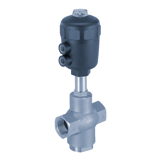
3/2-way globe valve
Hide thumbs
Also See for 2006:
- Operating instructions manual (23 pages) ,
- Quick start manual (36 pages)

Related Manuals for Burkert 2006


Summary of Contents for Burkert 2006
- Page 1 Type 2006 3/2-Way Globe Valve 3/2-Wege-Geradsitzventil Vanne à siège droit 3/2 voies Operating Instructions Bedienungsanleitung Manuel d‘utilisation...
- Page 2 We reserve the right to make technical changes without notice. Technische Änderungen vorbehalten. Sous réserve de modifications techniques. © Bürkert Werke GmbH & Co. KG, 2016 - 2017 Operating Instructions 1804/00_EU-EN_00810459 / Original DE...
-
Page 3: Table Of Contents
Type 2006 1 OPERATING INSTRUCTIONS ..............4 8 ASSEMBLY ....................14 Symbols ..................4 Safety instructions ..............14 Definition of the term "Device" ..........4 Before installation ..............14 Installation .................15 2 AUTHORIZED USE ..................5 Pneumatic connection ............17 3 BASIC SAFETY INSTRUCTIONS ............5 9 START-UP ...................... 18 Control pressure ..............18... -
Page 4: Operating Instructions
WARNING! Warns of a potentially dangerous situation. Definition of the term "Device" ▶ Failure to observe the warning may result in serious injuries or In these instructions, the term "device" always refers to the globe death. valve type 2006. english... -
Page 5: Authorized Use
AUTHORIZED USE BASIC SAFETY INSTRUCTIONS These safety instructions do not make allowance for any Non-authorized use of the globe valve type 2006 may be a hazard to people, nearby equipment and the environment. • contingencies and events which may arise during the installation, operation and maintenance of the devices. -
Page 6: General Information
The warranty is only valid if the device is used as authorized in accor- dance with the specified application conditions. Information on the Internet The operating instructions and data sheets for Type 2006 can be found on the Internet at: www.burkert.com... -
Page 7: Product Description
• Feedback indicator The device features mechanical limit switches or inductive prox- imity switches. General description The externally controlled globe valve type 2006 is suitable for liquid 5.2.2 Device versions and gaseous media. The globe valve is available for the actuator sizes ø 50 mm to ø 125 mm. -
Page 8: Structure And Function
Type 2006 StructureandFunction STRUCTURE AND FUNCTION Function Depending on the version, the lower seat of the valve is closed with Structure or against the medium flow. Spring force (CFA) or pneumatic control pressure (CFB and CFI) gen- The globe valve consists of a pneumatically actuated piston actuator erates the closing force on the closing body. - Page 9 Type 2006 StructureandFunction Control function A (CFA) Flow modes of operation In rest position line connector 1 closed by spring force. In rest position pressure connection 1 Flow Connection closed, working connection 2 relieved. modes of operation In rest position pressure connection 3 connected to working connection 2, relief 1 closed.
-
Page 10: Technical Data
Type 2006 TechnicalData TECHNICAL DATA Operating conditions 7.4.1 Temperature ranges Conformity Actuator Actuator Temperature ranges The globe valve type 2006 conforms with the EC Directives size material according to the EC Declaration of Conformity. Medium Environment [mm] (for PTFE seal) Standards 50, 63 –10... - Page 11 Type 2006 TechnicalData 7.4.2 Pressure ranges 7.4.3 Minimum control pressures Maximum control pressure: Minimum control pressure p , control function A: Actuator Actuator size Max. control pressure Actuator size Min. control pressure Orifice [mm] material [mm] [bar] [mm] [bar] 50...80 15, 20 15, 20 50...80 32, 40 Tab. 4: Maximum control pressure 32, 40 Maximum operating pressure, control function A: Tab.
- Page 12 Type 2006 TechnicalData CFA, ø 50 mm CFA, ø 80 mm Medium Medium pressure pressure [bar] [bar] Control Control pressure [bar] pressure [bar] Fig. 4: Pressure graph, actuator ø 50 mm, control function A Fig. 6: Pressure graph, actuator ø 80 mm, control function A CFA, ø...
-
Page 13: General Technical Data
Type 2006 TechnicalData General technical data CFA, ø 125 mm Control functions (CF) Medium Control function A Closed by spring force in rest position pressure [bar] Control function B Opened by spring force in rest position Control function I Actuating function via reciprocal... -
Page 14: Assembly
Type 2006 Assembly ASSEMBLY Before installation • Before connecting the valve, ensure the pipelines are flush. Safety instructions • Any installation position is possible, preferably with actuator face up. • Observe direction of flow (see type label). DANGER! Risk of injury from high pressure in the equipment. 8.2.1 Preparatory work ▶... -
Page 15: Installation
Type 2006 Assembly Installation 8.3.2 Installing the actuator WARNING! Graphite seal Risk of injury from improper installation. Assembly with unsuitable tools or non-observance of the tight- ening torque is dangerous as the device may be damaged. ▶ For installation use an open-end wrench, never a pipe wrench. - Page 16 Type 2006 Assembly → → Screw actuator into the valve body. For control function A pressurize the lower control air connection with compressed air (4 bar): Valve opens. Tightening torques: → Using a suitable open-end wrench, counter the wrench flat on...
-
Page 17: Pneumatic Connection
Type 2006 Assembly Pneumatic connection Control function A: On the lower connection of the actuator. DANGER! Control function B: On the upper connection of the actuator. Risk of injury from high pressure in the equipment. Control function I: ▶ Before dismounting pneumatic lines or valves, turn off the pres- On the upper and lower connections of the actuator. -
Page 18: Start-Up
Type 2006 Assembly START-UP To ensure complete opening of the upper valve seat, the minimum control pressure must be used. Observe the type label specifications and information on pressure and temperature values in section “7 Technical Data”. Flow direction below the lower seat (direction of flow 1 → 2) -
Page 19: Maintenance, Troubleshooting
Type 2006 Maintenance,Troubleshooting MAINTENANCE, WARNING! TROUBLESHOOTING For control function I: Danger if control pressure fails. For control function I control and resetting occur pneumatically. If 11.1 Safety instructions the pressure fails, no defined position is reached. ▶ To ensure a controlled restart, first pressurize the device with DANGER! control pressure, then switch on the medium. -
Page 20: Malfunctions
Type 2006 Maintenance,Troubleshooting 11.2.2 Cleaning Malfunction Remedial action Commercially available cleaning agents can be used to clean the Valve is not Dirt between seal and valve seat → outside. sealed Installing dirt trap NOTE! Seat seal worn → Installing new seat seals Avoid causing damage with cleaning agents. -
Page 21: Spare Parts
Valve set SET 6 consisting of the sealing and wearing parts of the actuator. (complete • Valve set (SET 6) spindle with consisting of the complete spindle with closing body. closing body) Order numbers see page 22. Fig. 12: Spare parts Type 2006 english... -
Page 22: Packaging, Transport, Storage
Type 2006 Packaging,Transport,storage Order numbers seal set for actuator (SET 5) PACKAGING, TRANSPORT, STORAGE Actuator size Matching Order no. Order no. valve sizes PA actuator PPS actuator NOTE! D (ø 50 mm) DN 15/20/25 233 588 233 582 Transport damages. E (ø 63 mm) DN 25-50 233 591 233 583 Inadequately protected equipment may be damaged during F (ø... - Page 24 www.burkert.com...
Need help?
Do you have a question about the 2006 and is the answer not in the manual?
Questions and answers