Burkert 2006 Operating Instructions Manual
3/2 way globe valve
Hide thumbs
Also See for 2006:
- Operating instructions manual (24 pages) ,
- Quick start manual (36 pages)

Subscribe to Our Youtube Channel
Related Manuals for Burkert 2006


Summary of Contents for Burkert 2006
- Page 1 Type 2006 3/2 way globe valve 3/2-Wege-Geradsitzventil Vanne à siège droit 3/2 voies Operating Instructions Bedienungsanleitung Manuel d‘utilisation...
- Page 2 We reserve the right to make technical changes without notice. Technische Änderungen vorbehalten. Sous réserve de modifications techniques. © Bürkert Werke GmbH & Co. KG, 2016 - 2019 Operating Instructions 1901/01_EU-ML_00810459 / Original DE...
-
Page 3: Table Of Contents
Type 2006 OPERATING INSTRUCTIONS ..........4 ASSEMBLY ................14 Symbols ............... 4 8.1 Safety instructions ............. 14 1.2 Definition of the term "Device" ........4 8.2 Before installation ............15 8.3 Installing the body ............. 15 AUTHORIZED USE ............... 5 8.4 Rotating the drive ............15 8.5 Pneumatic connection ..........16 BASIC SAFETY INSTRUCTIONS .......... -
Page 4: Operating Instructions
Type 2006 Operating Instructions OPERATING INSTRUCTIONS CAUTION The operating instructions describe the entire life cycle of the device. Warns of a possible danger. Keep these instructions in a location which is easily accessible ▶ Failure to observe this warning may result in a moderately to every user and make these instructions available to every new severe or minor injury. owner of the device. The operating instructions contain important safety NOTICE information. Warns of damage to property. -
Page 5: Authorized Use
Type 2006 Authorized Use AUTHORIZED USE BASIC SAFETY INSTRUCTIONS These safety instructions do not make allowance for any Non-authorized use of the globe valve type 2006 may be a • contingencies and events which may arise during the installation, hazard to people, nearby equipment and the environment. operation and maintenance of the devices. ▶ The device is designed for the controlled flow of liquid and gaseous media. • local safety regulations; the operator is responsible for observing ▶ In areas at risk of explosion, only use devices approved for these regulations, also with reference to the installation personnel use in those areas. These devices are labeled with a separate... - Page 6 Type 2006 Basic safety instructions To prevent damage to property of the device, ensure: Danger due to loud noises. ▶ Supply the media connections only with those media which ▶ Depending on the operating conditions, the device may generate are specified as flow media in the chapter entitled “7 Techni- loud noises. More detailed information on the likelihood of loud cal Data”. noises is available from the relevant sales office. ▶ Do not put any loads on the valve (e.g. by placing objects on ▶ Wear hearing protection when in the vicinity of the device. it or standing on it). Leaking medium when the packing gland is worn. ▶ Do not make any external modifications to the valves. Do not ▶ Regularly check relief bore for leaking medium.
-
Page 7: General Information
Type 2006 General Information GENERAL INFORMATION PRODUCT DESCRIPTION Contact addresses General description Germany The externally controlled globe valve type 2006 is suitable for liquid and gaseous media. Bürkert Fluid Control Systems Sales Center It uses neutral gases or air (control media) to control the flow-rate of Christian-Bürkert-Str. 13-17 water, alcohol, oil, fuel, hydraulic fluid, saline solution, lye, organic D-74653 Ingelfingen solvent and steam (flow media). Tel. + 49 (0) 7940 - 10 91 111 Properties Fax + 49 (0) 7940 - 10 91 448 E-mail: info@burkert.com • High tightness by self-adjusting packing glands (spindle sealing element). -
Page 8: Structure And Function
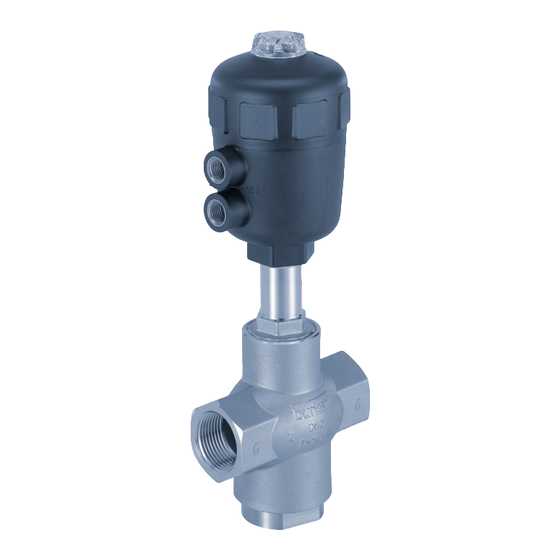
Type 2006 Structure and Function STRUCTURE AND FUNCTION 5.2.2 Device versions The globe valve is available for the actuator sizes ø 50 mm to ø Structure 125 mm. The globe valve consists of a pneumatically actuated piston actuator 5.2.3 Restrictions and a 3-way valve body. The actuator is manufactured from PA or WARNING PPS. The tried and tested, self-adjusting packing gland ensures high tightness. The flow-enhancing valve body made of stainless Risk of injury from water hammer. steel enables high flow values. A water hammer could crack the lines and device. ▶ Use valves with flow inlet above seat for gaseous media and Transparent cap with steam only. position indicator Actuator cover Actuator body Control air connection Nipple... -
Page 9: Function
Type 2006 Structure and Function Function Control function A (CFA) In rest position line connector 1 closed by spring force. Depending on the version, the lower seat of the valve is closed with or against the medium flow. Flow Connection Spring force (CFA) or pneumatic control pressure (CFB and CFI) modes of generates the closing force on the closing body. The force is operation transferred via a spindle which is connected to the actuator piston. WARNING For control function I – Danger if control pressure fails. -
Page 10: Technical Data
Type label In rest position pressure connection 3 connected to working connection Orifice Seal material 2, pressure connection 1 closed. Control function Body material Distribution valve Type In rest position pressure connection Port connection 2006 A 50,0 PTFE VA G1 1/2 2 connected to working connection Pilot pressure Pilot 6–10bar Pmed 1–2 : 9bar 3, working connection 1 closed. Pmed 2–3/1: 16bar Max. medium 00287199 pressure Tab. 2:... -
Page 11: Operating Conditions
Type 2006 Technical Data Operating conditions 7.4.2 Pressure ranges Maximum control pressure: 7.4.1 Temperature ranges Actuator Actuator size Max. control pressure Actuator Actuator Temperature ranges material [mm] [bar] size material Medium Environment 50...80 [mm] (for PTFE seal) 50, 63 –10... see “Fig. 3”... - Page 12 Type 2006 Technical Data 7.4.3 Minimum control pressures CFA, ø 50 mm Minimum control pressure p , control function A: Medium pressure Actuator size Min. control pressure Orifice [mm] [bar] [mm] [bar] 15, 20 15, 20 Control 32, 40 pressure [bar] 32, 40 Fig. 4: Pressure graph, actuator ø 50 mm, control function A CFA, ø 63 mm...
- Page 13 Type 2006 Technical Data CFA, ø 80 mm CFA, ø 125 mm Medium Medium pressure pressure [bar] [bar] Control Control pressure [bar] pressure [bar] Fig. 6: Pressure graph, actuator ø 80 mm, control function A Fig. 8: Pressure graph, actuator ø 125, control function A CFA, ø 100 mm Medium pressure...
-
Page 14: General Technical Data
Type 2006 Assembly General technical data ASSEMBLY Control functions (CF) Safety instructions Control function A Closed by spring force in rest position DANGER Control function B Opened by spring force in rest position Risk of injury from high pressure in the equipment. Control function I Actuating function via reciprocal pressurization ▶ Before dismounting pneumatic lines or valves, turn off the pressure and vent the lines. Materials WARNING Body Stainless steel 316L Actuator PA, PPS Risk of injury from improper assembly. -
Page 15: Before Installation
Type 2006 Assembly → Clamp the valve body into a holding device (applies only to ▶ Do not transport, install or remove heavy devices without the valves not yet installed). aid of a second person and using suitable auxiliary equipment. → For control function A pressurize the lower control air connection ▶ Use appropriate tools. with compressed air (4 bar): Valve opens. Before installation → Using a suitable open-end wrench, counter the wrench flat on the pipe. → Before connecting the valve, ensure the pipelines are flush. → Place a suitable open-end wrench on the hexagon of the actuator → Observe direction of flow (see type label). (see “Fig. 9”). -
Page 16: Pneumatic Connection
Type 2006 Assembly Pneumatic connection Control function A: On the lower connection of the actuator. DANGER Control function B: On the upper connection of the actuator. Risk of injury from high pressure in the equipment. Control function I: ▶ Before dismounting pneumatic lines or valves, turn off the On the upper and lower connections of the actuator. pressure and vent the lines. Pressure on the lower connection opens the valve, WARNING pressure on the upper connection closes the valve. Risk of injury from unsuitable connection hoses. -
Page 17: Start-Up
Type 2006 Assembly START-UP To ensure complete opening of the upper valve seat, the minimum control pressure must be used. Observe the type label specifications and information on pressure and temperature values in section “7 Technical Data”. Flow direction below the lower seat (direction of flow 1 → 2) Control pressure Control function A (CFA) closes by spring force against the medium WARNING flow. Control function B (CFB) closes with the control pressure against For control function I: Danger if control pressure fails. the medium flow. The medium pressure supports the opening of If the pressure fails, no defined position is reached. -
Page 18: Maintenance, Troubleshooting
Type 2006 Maintenance, Troubleshooting MAINTENANCE, For control function I: Danger if control pressure fails. TROUBLESHOOTING For control function I control and resetting occur pneumati- cally. If the pressure fails, no defined position is reached. 11.1 Safety instructions ▶ To ensure a controlled restart, first pressurize the device with control pressure, then switch on the medium. DANGER 11.2 Maintenance work Risk of injury from high pressure in the equipment. ▶ Before dismounting pneumatic lines or valves, turn off the Actuator: pressure and vent the lines. -
Page 19: Malfunctions
Type 2006 Maintenance, Troubleshooting 11.3 Malfunctions 11.2.1 Recommended maintenance intervals The valve should be visually inspected once a year. Shorter Malfunction Remedial action maintenance intervals are recommended depending on appli- Actuator Control air connection interchanged cation conditions. The visual inspection includes the pneumatic does not connections and the medium connections as well as the deaer- CFA: Connect lower control air connection switch ation bore in the pipe. CFB: Connect upper control air connection 11.2.2 Cleaning CFI: L ower control air connection: Open Upper control air connection: Close Commercially available cleaning agents can be used to clean the Control pressure too low outside. → See pressure specifications on the type NOTICE label Avoid causing damage with cleaning agents. -
Page 20: Spare Parts
Type 2006 Spare Parts SPARE PARTS Malfunction Remedial action Valve is not Dirt between seal and valve seat CAUTION sealed → Installing dirt trap Risk of injury and/or damage by the use of incorrect parts. Seat seal worn Incorrect accessories and unsuitable spare parts may cause → Installing new seat seals injuries and damage the device and the surrounding area. - Page 21 288 384 Valve set SET 6 (complete E (ø 63 mm) 288 386 spindle with E (ø 63 mm) 288 392 closing body) F (ø 80 mm) 288 393 H (ø 125 mm) 288 394 E (ø 63 mm) 288 395 F (ø 80 mm) 288 393 H (ø 125 mm) 288 394 Fig. 11: Spare parts Type 2006 H (ø 125 mm) 288 399 english...
-
Page 22: Packaging, Transport, Storage
Type 2006 Packaging, Transport, Storage PACKAGING, TRANSPORT, STORAGE NOTICE Transport damages. Inadequately protected equipment may be damaged during transport. ▶ During transportation protect the device against wet and dirt in shock-resistant packaging. ▶ Avoid exceeding or dropping below the permitted storage temperature. Incorrect storage may damage the device. ▶ Store the device in a dry and dust-free location. ▶ Storage temperature -20 … +65 °C. Damage to the environment caused by device components contaminated with media. - Page 23 www.burkert.com...
Need help?
Do you have a question about the 2006 and is the answer not in the manual?
Questions and answers