Table of Contents
Advertisement
Quick Links
Advertisement
Table of Contents

Subscribe to Our Youtube Channel
Related Manuals for Burkert 623969


Summary of Contents for Burkert 623969
- Page 1 Type 2000 2/2-way angle seat valve Operating Instructions...
- Page 2 We reserve the right to make technical changes without notice. © Bürkert Werke GmbH & Co. KG, 2008 - 2021 Operating Instructions 2106/19_ENen 00893086 / Original DE...
-
Page 3: Table Of Contents
Type 2000 Contents CONTENTS 1 About these instructions .......................... 5 Symbols............................ 5 Definition of terms .......................... 6 2 Intended use ............................... 7 3 Basic safety instructions.......................... 8 4 General information.......................... 10 Contact address .......................... 10 Warranty ............................ 10 Information on the Internet ...................... 10 5 Product description.......................... 11 Features............................ - Page 4 Type 2000 Contents 8 Start-up .............................. 29 9 Deinstallation ............................ 30 10 Servicing .............................. 31 10.1 Safety instructions maintenance .................... 31 10.2 Maintenance work .......................... 31 10.2.1 Actuator .......................... 31 10.2.2 Wearing parts........................ 32 10.2.3 Visual inspection ........................ 32 10.2.4 Cleaning .......................... 32 11 Faults ................................ 33 12 Replacement parts, accessories ...................... 34 12.1 Installation tools..........................
-
Page 5: About These Instructions
Type 2000 About these instructions ABOUT THESE INSTRUCTIONS The operating instructions describe the entire life cycle of the device. Keep these instructions ready to hand at the operation site. Important safety information! ▶ Carefully read these instructions. ▶ Observe in particular the safety instructions, intended use and operating conditions. ▶... -
Page 6: Definition Of Terms
Type 2000 About these instructions Definition of terms In these instructions the term "device" denotes the following device types: 2/2-way angle seat valve Type 2000 The abbreviation “Ex” used in these instructions always stands for “potentially explosive atmosphere”. The term “büS” (Bürkert system bus) used in this manual refers to the communication bus developed by Bürkert, based on the CANopen protocol. -
Page 7: Intended Use
Type 2000 Intended use INTENDED USE The angle seat valve Type 2000 is designed to control the flow rate of media. The permitted media are lis- ted in the "Technical data". ▶ Use the device for its intended purpose only. Non-intended use of the device may be dangerous to people, nearby equipment and the environment. -
Page 8: Basic Safety Instructions
Type 2000 Basic safety instructions BASIC SAFETY INSTRUCTIONS These safety instructions do not take into account any unforeseen circumstances and events which occur during installation, operation and maintenance. The operator is responsible for observing the location-specific safety regulations, also with reference to the personnel. - Page 9 Type 2000 Basic safety instructions To prevent injuries, observe the following: ▶ Secure device or plant to prevent unintentional activation. ▶ Only trained technicians may perform installation and maintenance work. ▶ Perform installation and maintenance with suitable tools only. ▶ Heavy equipment must only be transported, assembled, installed or dismantled with the help of a second person as appropriate and using suitable apparatus.
-
Page 10: General Information
Phone: + 49 (0) 7940 - 10 91 111 Fax: + 49 (0) 7940 - 10 91 448 E-mail: info@burkert.com International The contact addresses can be found on the back pages of the printed Quickstart. Also on the Internet at: http://www.burkert.com... -
Page 11: Product Description
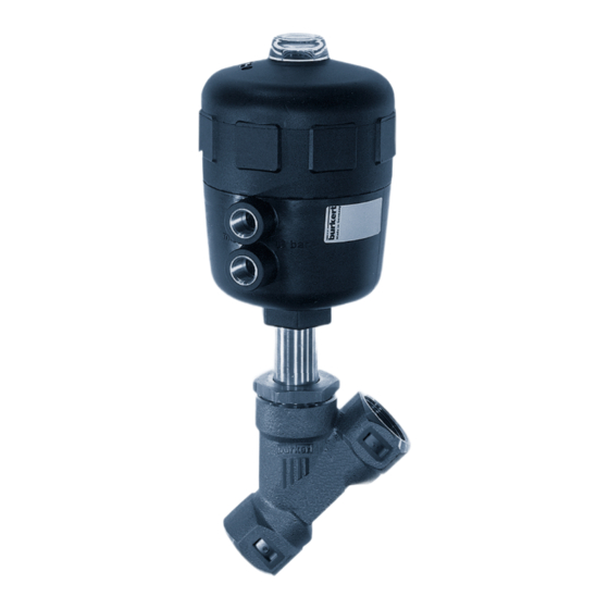
Type 2000 Product description PRODUCT DESCRIPTION The device is specially optimised for decentralised process automation and meets all the relevant require- ments, even under difficult usage conditions. Its design enables the easy integration of automation modules in all extension stages, whether they are electrical/optical position feedback, pneumatic control units, or even an integrated fieldbus interface. - Page 12 Type 2000 Product description Transparent cap with position indicator Actuator cover Pilot air ports Actuator housing Port connection Characters for designation Angle seat body of flow direction Type 2000 Fig. 1: Structure and description Control function Definition Circuit symbol Figure 2 (A),(P) A (CFA) Closed by spring force in rest position.
-
Page 13: Flow Direction Below Seat
Type 2000 Product description 5.2.1 Flow direction below seat WARNING! Valve seat not sealed when control pressure too low or operating pressure too high. If control pressure for control function B and control function I is too low or operating pressure is too high, this can cause the valve seat to leak. -
Page 14: Device Options
Type 2000 Product description Device options ▪ Stroke limit Limiting the maximum or minimum flow rate volume with an adjusting screw. ▪ Control unit Different variants are available depending on the requirement. ▪ Position feedback The device is available with mechanical limit switches or inductive proximity switches. Variants Information on the variants of the device can be found in the data sheet at https://www.burk- ert.com/en or in your sales department. -
Page 15: Technical Data
Type 2000 Technical data TECHNICAL DATA Conformity The device conforms to the EC directives as per the EC Declaration of Conformity (if applicable). Standards The applied standards, which are used to demonstrate conformity with the directives, are listed in the EU type examination certificate and/or the EU Declaration of Conformity (if applicable). -
Page 16: Temperature Ranges
Type 2000 Technical data 6.4.1 Temperature ranges Actuator size [mm] Actuator material Medium temperature (for PTFE Ambient temperature [°C] seal) [°C] ø 40 … ø 63 −10...see Fig. 5 −10...see Fig. 5 ø80...ø125 −10...+185 −10...+60 ø40...ø80 −10...see Fig. 6, 7 +5...+140 ø100...ø125 −10...see Fig. - Page 17 Type 2000 Technical data Temperature [°C] Pressure (bar) −10 … +50 14.0 14.0 13.4 12.4 11.7 Tab. 6: Derating the operating pressure as per JIS B 2220 10K Usage limits of the temperature Service life is reduced if the valves are used at a maximum ambient temperature of +140 °C. 80 100 120 140 160 180 200 220 Medium temperature [°C] Fig. 6: Derating CLASSIC ANTG40...
-
Page 18: Pressure Ranges
Type 2000 Technical data 80 100 120 140 160 180 200 220 Medium temperature [°C] Fig. 8: Derating CLASSIC ANTG100, 125 See also 2 Temperature ranges [} 16] 6.4.2 Pressure ranges Actuator material Actuator size [mm] Max. Pilot pressure [bar] ø40...ø100 ø125 ø40...ø80 ø100...ø125 Tab. 7: Maximum pilot pressure... - Page 19 Type 2000 Technical data ø40 CFB/CFI Pilot pressure [bar] Fig. 9: Actuator ø 40 mm, control function B and I, flow direction below the seat ø50 CFB/CFI Pilot pressure [bar] Fig. 10: Actuator ø 50 mm, control function B and I, flow direction below the seat ø63 CFB/CFI Pilot pressure [bar] Fig. 11: Actuator ø 63 mm, control function B and I, flow direction below the seat ø80 CFB/CFI...
- Page 20 Type 2000 Technical data ø100 CFB/CFI Pilot pressure [bar] Fig. 13: Actuator ø 100 mm, control function B and I, flow direction below the seat ø125 CFB/CFI Pilot pressure [bar] Fig. 14: Actuator ø 125 mm, control function B and I, flow direction below the seat Minimum control pressure when flow direction above the seat (Medium flow in valve closing direction) Required minimum control pressure depending on the operating pressure The following graphs show the required minimum control pressure for the respective control function de-...
- Page 21 Type 2000 Technical data ø50 Pilot pressure [bar] Fig. 16: Actuator ø 50 mm, control function A, flow direction above the seat ø63 Pilot pressure [bar] Fig. 17: Actuator ø 63 mm, control function A, flow direction above the seat ø80 Pilot pressure [bar] Fig. 18: Actuator ø 80 mm, control function A, flow direction above the seat ø100 Pilot pressure [bar] Fig. 19: Actuator ø 100 mm, control function A, flow direction above the seat...
-
Page 22: Mechanical Data
Type 2000 Technical data ø125 Pilot pressure [bar] Fig. 20: Actuator ø 125 mm, control function A, flow direction above the seat Mechanical data Actuator size See type label Installation position any, preferably actuator face up Materials Threaded connection Red bronze Stainless steel 316L Welded connection and clamp connec- Stainless steel 316L tion... -
Page 23: Installation
Type 2000 Installation INSTALLATION Safety instructions installation DANGER! Risk of injury from high pressure and discharge of medium. ▶ Before working on the device or system, switch off the pressure. Vent or drain lines. WARNING! Risk of injury due to improper installation. ▶... -
Page 24: Preparatory Work
Type 2000 Installation Preparatory work Observe flow direction on the type label. Remove soiling from pipelines. Ensure that pipelines are in alignment. 7.2.1 Attach dirt trap Dirt trap for devices with approval according to DIN EN 161 According to DIN EN 161 "Automatic shut-off valves for gas burners and gas appliances", a dirt trap, which prevents the penetration of a 1 mm test pin, must be installed upstream of the valve. -
Page 25: Removing Actuator From The Valve Body For Devices With Installed Control Unit
Type 2000 Installation For control function A pressurise the pilot air port 1 with compressed air (5 bar). Valve opens. For control function A with pilot valve: Manually switch device with pilot valve. To do this, follow the op- erating instructions for the control unit. Valve opens. Place a suitable open-end wrench on the wrench flat of the body connection. -
Page 26: Installing Control Unit
Type 2000 Installation Screw actuator into the valve body. Observe tightening torques of the following table. Seat size Tightening torque [Nm] 45 ±3 50 ±3 60 ±3 65 ±3 65 ±3 70 ±3 70 ±3 120 ±5 Tab. 9: Tightening torques valve body and body connection Installing control unit Description see chapter "Installation"... -
Page 27: Connecting Device Pneumatically
Type 2000 Installation For control function A und I pressurise lower pilot air port with compressed air. Counter with a suitable open-end wrench on the wrench flat of the body connection. Place a suitable open-end wrench on the hexagon head of the actuator. DANGER! Risk of injury from high pressure and discharge of medium. - Page 28 Type 2000 Installation Control function I: Connect control medium to pilot air port at the top and bottom. Pressure on top connector closes the valve. Pressure on bottom connector opens the valve. Control function Pilot air port Bottom Pilot air connection Bottom Closes...
-
Page 29: Start-Up
Type 2000 Start-up START-UP DANGER! For control function I: Danger due to the control pressure failing. If the control pressure fails, the valve remains in an undefined position. ▶ For a controlled restart, pressurize the device with control pressure and then connect the medium. WARNING! Risk of injury from high pressure or hot medium. -
Page 30: Deinstallation
Type 2000 Deinstallation DEINSTALLATION DANGER! Risk of injury from high pressure and discharge of medium. ▶ Before working on the device or system, switch off the pressure. Vent or drain lines. Loosen pneumatic connection. Disassemble the device. -
Page 31: Servicing
Type 2000 Servicing SERVICING 10.1 Safety instructions maintenance DANGER! Risk of injury from high pressure and discharge of medium. ▶ Before working on the device or system, switch off the pressure. Vent or drain lines. DANGER! For control function I: Danger due to the control pressure failing. If the control pressure fails, the valve remains in an undefined position. -
Page 32: Wearing Parts
Type 2000 Servicing 10.2.2 Wearing parts The following parts are subject to natural wear: ▪ Seal ▪ Swivel plate If leaks occur, replace the respective wearing part. 10.2.3 Visual inspection According to the usage conditions, perform regular visual inspections: Check medium ports for tightness. Check relief bore on the pipe for leaks. -
Page 33: Faults
Type 2000 Faults FAULTS Fault Cause Elimination Actuator does not switch Pilot air port inter- Connect pilot air port at bottom changed Connect pilot air port at top Pilot air port at bottom: Open, pilot air port at top: closing Pilot pressure too low Observe pressure specifications on the type label Operating pressure too... -
Page 34: Replacement Parts, Accessories
Type 2000 Replacement parts, accessories REPLACEMENT PARTS, ACCESSORIES CAUTION! Risk of injury and/or damage due to the use of incorrect parts. Incorrect accessories and unsuitable spare parts may cause injuries and damage the device and its envir- onment. ▶ Use original accessories and original spare parts from Bürkert only. 12.1 Installation tools Installation wrench for packing gland (series-production status up to January 2013) -
Page 35: Spare Parts For Seal Set For Set 5 Actuator
Type 2000 Replacement parts, accessories Seal set for actuator SET 5 Valve set SET 6 Fig. 25: Spare parts for angle seat valve 12.3 Spare parts for seal set for SET 5 actuator PA actuator Actuator size Matching valve sizes Order no. Order no. -
Page 36: Spare Parts For Valve Set Set 6
Type 2000 Replacement parts, accessories PPS actuator Actuator size Body DN Order no. for stand- Order no. for hot Order no. for high ard version water version (up to temperature version 200 °C) (up to 230 °C) C (ø 40) DN15/20/25 233581 C (ø40) DN15/20/25 288013... - Page 37 Type 2000 Replacement parts, accessories Order no. Order no. (PTFE seal) (FKM seal) 160737 168816 011208 011262 011209 011267 233813 233817 233815 233818 350831 Tab. 17: SET 6; Stainless steel valve body SET 6 with PEEK seal on request. Actuator size ø63...
-
Page 38: Transportation, Storage, Disposal
Type 2000 Transportation, storage, disposal TRANSPORTATION, STORAGE, DISPOSAL ATTENTION! Damage in transit due to inadequately protected devices. ▶ Protect the device against moisture and dirt in shock-resistant packaging during transportation. ▶ Observe permitted storage temperature. ATTENTION! Incorrect storage may damage the device. ▶...
Need help?
Do you have a question about the 623969 and is the answer not in the manual?
Questions and answers