Page 1
2019 Force / Sensor Owner’s Manual Supplement READ THIS SUPPLEMENT AND YOUR GT BICYCLE OWNER’S MANUAL. Both contain important safety information. Keep both for future reference.
Page 2
Safety Messages In this supplement, particularly important information is presented in the following ways: Indicates a hazardous situation which, if not avoided, may result in death or serious injury. NOTICE Indicates special precautions that must be taken to avoid damage. The following symbols are used in this manual: Symbol Name...
Page 3
7570 GC, OLDENZAAL, Netherlands your warranty. Tel: +41 61 551 14 80 Fax:+31 54 151 42 40 International Distributors Consult the following websIte to identify the appropriate GT Dealer for your region. 134937 Rev 1.
· An unusual or strange feel to (frame, stem, fork, handlebar, seat the frame post, etc.) Ask your GT Dealer for · Carbon which has a soft feel or help. altered shape We urge you to read PART II, ·...
Page 5
To minimize risk we strongly recommend that owners always Please read your GT Bicycle have mechanical work done by Owner’s Manual for more an Authorized GT Dealer. information about Intended Use and Conditions 1-5. 134937 Rev 1.
Your retailer MUST follow and observe this specification for your bike. For Maximum Fork Length specifications for GT bicycles, see www.gtbikes.com. You can be severely injured, paralyzed or killed in an accident if you ignore this warning.
Page 7
English Tire Size x Maximum Width Observe the Tire Size x Maximum Width for your bike found in the “Specifications” page of this manual. Mounting the wrong size tires can result in the tires hitting the fork or frame when riding. If this happens, you can lose control of your bike and you can be thrown off, a moving tire can be stopped because it touches the fork or frame.
Page 8
Force / Sensor - Owners Manual Supplement Rear Shocks Minimum Seat Post Insert Select only compatible shocks Make sure at least 100 mm of and forks for your bike. Do not the seat post is inserted into the modify your bike in any way to frame at all times.
English TECHNICAL INFORMATION Specifications Item Specification Model Force Sensor Wheel Size 27.5 in 29 in Rear Travel 150 mm 130 mm Head Tube UPR: 1-1/8 in, LWR: 1-1/2 in Headset Integrated, 1-1/8 in - 1-1/2 in Bottom Bracket: Type/ Width BSA / 73 mm Front Derailleur Seat Post: Dia./Binder...
The orientation of the Flip Chip does not influence SAG. Force Sensor 12.5 mm 12 mm Link Rear Shock O-Ring Flip Chip NOTICE Mount shocks in orientation shown: reservoir/controls forward and facing up as shown. Consult your GT Dealer. 134937 Rev 1.
Page 13
English Flip Chip Orientation The orientation of the Flip Chip will change the bottom bracket height, head tube angle, seat tube angle. Resulting changes to the values can be found in the “Geometry“ section. Shock Bolt Shock Bolt Socket 8 N·m Chip marking faces out...
Page 14
Force / Sensor - Owners Manual Supplement Link Assembly Spacers smooth side small end 5 N·m 5 N·m Bearings small end 5 N·m Connecting the Link To prevent mis-alignment and/or potential damage, follow this assembly order routine: Connect link to frame with the LockR pivot. Connect the rear shock, make sure the smooth side of the spacers face the shock.
Page 15
English Bearings grooves inner lip Circlip Bearings Circlip Inspection • The condition of the bearings, should be inspected periodically. These are normal wear parts so plan to have them replaced as they wear-out. • To inspect the bearings, disconnect the link to expose the bearings. Rotate the inner race of each bearing with your finger.
Page 16
Force / Sensor - Owners Manual Supplement Dropouts Chain Stay 7 N·m Seat Stay small end Pivot Axles Spacers Bearings • When connecting the seat stays to the chain stay, make sure the small end of spacers face the bearings . The flat side of the spacers should face out, as shown.
Page 17
English Circlip Bearing Bearing Circlip • The condition of the bearings, pivot axles, and spacers should be inspected periodically. These are normal wear parts so plan to have them replaced as they wear-out. • To inspect the bearings, remove the pivot to expose the bearings. There are two bearings in each dropout.
Page 18
Force / Sensor - Owners Manual Supplement LockR Be sure to support the bike or swingarm to prevent personal injury or bike damage when removing/disconnecting linkages of an axle. To remove the LockR from the frame: 1. Loosen the screw 4-6 turns using a T25 Torx key. 2.
Page 19
English DO NOT INSTALL ASSEMBLED N·m N·m N·m N·m Insert 5mm & Unthread Unthread & dislodged & turn to free Remove tap mallet remove Remove 134937 Rev 1.
Page 20
Force / Sensor - Owners Manual Supplement Hanger Replacement 2 N·m KG0007N02 - (Direct Mount) Bolts Hangers KG0006N02 (Standard) • Before installing a new hanger, be sure to clean any dirt or debris on the dropout with a nylon brush (old toothbrush). •...
Page 21
English ISCG Tab Instructions BB Cup K22059 ISCG Bracket • On alloy frame models, the ISCG mounting tabs are fixed permanently to the frame and cannot be removed • On carbon frames, the ISCG mount fits onto a spline. Correct positioning is certain due to the splines alignment.
Page 23
English Standard Direct Mount 8 N·m 2 N·m 5 N·m 5 N·m 7 N·m 5 N·m 1 N·m Part Number Description FORCE SENSOR K36069 Force Suspension Link 27.5 BLK ✔ K36059 Sensor Suspension Link 29/27.5+ BLK ✔ K36028 Force/Sensor Link CS Hardware ✔...
Force / Sensor - Owners Manual Supplement Tightening Torques Correct tightening torque for the fasteners (bolts, screws, nuts) on your bicycle is very important to your safety, durability, and performance of your bicycle. We urge you to have your dealer correctly torque all fasteners using a torque wrench.
Page 25
English MAINTENANCE The following table lists only supplemental maintenance items. Please consult your GT Bicycle Owner’s Manual for more information on basic bike maintenance. Item Frequency Cable Routing - Make sure control cables are in place, Before first ride undamaged and attached securely.
Page 26
Force / Sensor - Owners Manual Supplement NOTES Use this page to write /record important information about your bike : (e.g. maintenance history, dealer contact information, settings, etc.) 134937 Rev 1.
Need help?
Do you have a question about the Force 27.5 and is the answer not in the manual?
Questions and answers
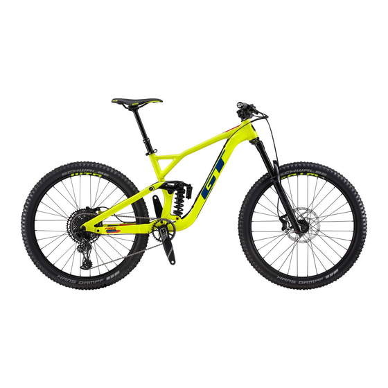
What is the name of this bolt in the image bellow
The name of the bolt for the GT Force 27.5 is "LTS Shock Bolts/Flip Chips."
This answer is automatically generated