Table of Contents
Advertisement
Advertisement
Table of Contents

Related Manuals for Siemens SINAMICS IOP-2


Summary of Contents for Siemens SINAMICS IOP-2
- Page 3 Fundamental safety ___________________ instructions ___________________ Safety notes ___________________ SINAMICS Overview ___________________ Installation Intelligent Operating Panel 2 (IOP-2) ___________________ Wizards menu ___________________ Control menu Operating Instructions ___________________ Menu ___________________ Options ___________________ Technical data Edition 04/2017, Firmware IOP-2 V2.0 04/2017, FW V2.0 A5E39549448B AA...
- Page 4 Note the following: WARNING Siemens products may only be used for the applications described in the catalog and in the relevant technical documentation. If products and components from other manufacturers are used, these must be recommended or approved by Siemens. Proper transport, storage, installation, assembly, commissioning, operation and maintenance are required to ensure that the products operate safely and without any problems.
-
Page 5: Table Of Contents
Table of contents Fundamental safety instructions ......................7 General safety instructions ....................... 7 Industrial security ........................8 Safety notes ............................9 Warnings and cautions ......................9 Overview............................... 11 Introduction ..........................11 Layout and functions ....................... 12 Screen icons ........................... 15 Menu structure ........................ - Page 6 Table of contents Extras Menu ........................... 51 Options ..............................63 Door mounting kit ........................63 Hand-held device ........................65 Technical data ............................69 Technical specifications ......................69 Index ..............................71 Intelligent Operating Panel 2 (IOP-2) Operating Instructions, 04/2017, FW V2.0, A5E39549448B AA...
-
Page 7: Fundamental Safety Instructions
Fundamental safety instructions General safety instructions WARNING Danger to life if the safety instructions and residual risks are not observed If the safety instructions and residual risks in the associated hardware documentation are not observed, accidents involving severe injuries or death can occur. •... -
Page 8: Industrial Security
Siemens’ products and solutions undergo continuous development to make them more secure. Siemens strongly recommends to apply product updates as soon as available and to always use the latest product versions. Use of product versions that are no longer supported, and failure to apply latest updates may increase customer’s exposure to cyber threats. -
Page 9: Safety Notes
Safety notes Warnings and cautions Warnings and cautions DANGER Ensuring a safe and stable state During commissioning of the converter it is essential to ensure that the system is in a safe and stable state, as some commissioning processes have the potential to start the motor. Therefore it is important to secure any loads and ensure that should the motor start, no potentially dangerous conditions exist. - Page 10 Safety notes 2.1 Warnings and cautions Intelligent Operating Panel 2 (IOP-2) Operating Instructions, 04/2017, FW V2.0, A5E39549448B AA...
-
Page 11: Overview
Overview Introduction Compatibility The Intelligent Operator Panel 2 (IOP-2) has been designed to enhance the interface and communications capabilities of SINAMICS Inverters. The IOP-2 connects to the Inverter through an RS232 interface. It has been designed to automatically recognize the following devices from the SINAMICS range: ●... -
Page 12: Layout And Functions
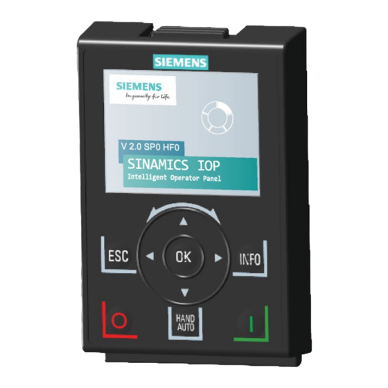
Overview 3.2 Layout and functions Layout and functions Overview The physical layout of the IOP-2 is shown below: Figure 3-1 Layout of the IOP-2 Intelligent Operating Panel 2 (IOP-2) Operating Instructions, 04/2017, FW V2.0, A5E39549448B AA... - Page 13 Overview 3.2 Layout and functions The IOP-2 is operated by using a Sensor Control Field and five additional buttons. The specific functions of the Sensor Control Field and buttons are shown in the table below. Table 3- 1 Function of the IOP-2 controls Function The Sensor Control Field has the following functions: In a menu, sliding your finger around the Sensor Control Field changes the selection.
- Page 14 Overview 3.2 Layout and functions Function The INFO key has the following functions: Displays additional information for the currently selected item. • Pressing the INFO key again will display the previous screen. • Pressing the INFO key during power-up of the IOP-2 will place the IOP-2 in DEMO mode. To exit DEMO •...
-
Page 15: Screen Icons
Overview 3.3 Screen icons Screen icons Overview The IOP-2 displays a number of icons at the top right-hand edge of the display to indicate various states or current conditions of the converter. These icons are explained in the table below. Table 3- 2 Screen icons Function... - Page 16 Overview 3.3 Screen icons Screen faults and alarm indicators When a fault or an alarm is active on the converter the top label on the screen will turn red. The top label will remain red until the fault or warning has been acknowledged or rectified. Figure 3-2 Fault and alarm notifications Use of screen colours...
-
Page 17: Menu Structure
Overview 3.4 Menu structure Menu structure Overview The Menu structure of the IOP-2 is shown in the figure below. Figure 3-3 IOP-2 menu structure Intelligent Operating Panel 2 (IOP-2) Operating Instructions, 04/2017, FW V2.0, A5E39549448B AA... - Page 18 Overview 3.4 Menu structure Intelligent Operating Panel 2 (IOP-2) Operating Instructions, 04/2017, FW V2.0, A5E39549448B AA...
-
Page 19: Installation
Installation Fitting the IOP-2 Fitting the IOP-2 to the Control Unit Note IOP-2 power supply The IOP-2 has no internal power supply and derives its power directly from the Control Unit of the converter through the RS232 interface. The IOP-2 can also be connected to a PC and derives its power through the USB connection. -
Page 20: Initial Set-Up
Installation 4.2 Initial set-up Initial set-up Initial set-up sequence Once the IOP-2 is fitted and powered-up it will automatically detect the type of Control Unit and Power Module to which it has been fitted. On first-time use, the IOP-2 automatically displays the option to select the default language and allow the time and date to be set (if the Control Unit to which the IOP-2 is fitted has a real-time clock). - Page 21 Installation 4.2 Initial set-up Language selection The IOP-2 on first start-up will display the langauge screen for the user to select their required language, should you wish to select you language manually, the following actions should be performed: Select Menu Select Extras Select Panel settings Select language...
- Page 22 Installation 4.2 Initial set-up Select Time and date Set the Time and date Set time and date settings settings Press and hold down ESC for Status Screen The settings for time are normally done on the Control Unit if it has a Real-time Clock (RTC). If the Inverter has an RTC the IOP-2 will take its settings from the Control Unit.
- Page 23 Installation 4.2 Initial set-up Select Lighting duration Select Lighting duration time Press and hold down ESC for Status Screen Note Screen will flash when an active fault condition exists When an active fault condition exists on the IOP-2, if no key has been pressed for more than one minute then the screen will start to flash on and off.
-
Page 24: User Definable Labels On Status Screen
Installation 4.3 User definable labels on status screen User definable labels on status screen User definable labels User defined labels allow the user to customize the labels that appear on the status screen of the IOP-2. There are a maximum of four labels that can be defined and they are located on the IOP-2 in the "cps"... -
Page 25: Firmware Upgrade
The English language file is essential to the correct functioning of the IOP-2 and therefore cannot be deleted. The IOP-2 firmware files can be downloaded from the Siemens Service and Support website at the following link: IOP-2 firmware download: IOP-2 Firmware upgrade (http://support.automation.siemens.com/WW/view/en/67273266) - Page 26 Installation 4.4 Firmware upgrade Intelligent Operating Panel 2 (IOP-2) Operating Instructions, 04/2017, FW V2.0, A5E39549448B AA...
-
Page 27: Wizards Menu
The wiring diagrams and additional information for the configuration of the drives when using the IOP Wizard is given in the IOP Wizard Manual. This manual is available for download at the following link: IOP Wizard Manual (https://support.industry.siemens.com/cs/de/en/view/109483443) Intelligent Operating Panel 2 (IOP-2) Operating Instructions, 04/2017, FW V2.0, A5E39549448B AA... -
Page 28: Example Wizard
Wizards menu 5.1 Example Wizard Example Wizard Overview of wizards The following example of how wizards work on the IOP-2 are purely for demonstration purpose only. CAUTION Before commissioning an application Prior to using a wizard, it is essential that the user's Control Unit and Power Module have been installed and wired correctly, in accordance with the requirements of the user's application. - Page 29 For further information, see the relevant Operating Instructions. For more detailed information of the application classes, see the document at the link below: Application classes (https://support.industry.siemens.com/cs/ww/en/view/109480663) Intelligent Operating Panel 2 (IOP-2) Operating Instructions, 04/2017, FW V2.0, A5E39549448B AA...
-
Page 30: Basic Commissioning With The Iop-2
Wizards menu 5.1 Example Wizard 5.1.1 Basic commissioning with the IOP-2 Basic commissioning wizard NOTICE Requirements prior to using the Basic Commissioning Wizard • The user must be fully conversant with all safety instructions as detailed in the "Fundamental Safety Instructions" section of the Operating Instructions for your converter. - Page 31 Wizards menu 5.1 Example Wizard Select Continue Select Application Class Select Motor Data Select Enter Motor Data Select Motor Type Select Characteristic Select Continue Input Motor Frequency Input Motor Voltage Input Motor Current Input Power Rating Input Motor Speed Intelligent Operating Panel 2 (IOP-2) Operating Instructions, 04/2017, FW V2.0, A5E39549448B AA...
- Page 32 Wizards menu 5.1 Example Wizard Select Technology Select required Motor Data Select Macro Source Application ID function Input the Minimum Input Maximum Frequency Input Ramp-up time Frequency Input Ramp-down time Summary of Settings - Select Save Settings Continue Settings saved Status Screen displayed On first ON command - Motor ID is performed...
-
Page 33: Control Menu
Control menu Overview The Control menu allows the user to change the following settings in real-time: ● Setpoint ● Reverse ● Jog ● Custom Hand mode ● Startup in Hand mode ● Hand/Auto disable The control menu is accessed from the menu at the bottom-centre of the Status screen, as shown below. -
Page 34: Setpoint
Control menu 6.1 Setpoint Setpoint Setting the Setpoint The setpoint value determines the speed at which the motor runs as a percentage of its full range of motion. To change the setpoint, the following actions should be performed: Select Control Select Setpoint Use Touch-wheel to set the Setpoint... -
Page 35: Jog
Control menu 6.3 Jog Setting Jog The Jog function, when selected will allow the motor to be manually rotated by a pre- determined value with each press of . If is pressed continuously, the motor will rotate continuously until is released. To enable or disable the Jog function, the following actions should be performed: Select Control Select Jog... - Page 36 Control menu 6.4 Custom Hand mode An example of setting up the custom hand mode is given in the instructions below. Table 6- 1 Interconnection inputs for Status Word 1 in Custom Hand mode Standard interconnection r8540 STW 1 from IOP-2 Binector Inputs (BI) p8542 Effective STW1 in Custom Hand...
-
Page 37: Startup In Hand Mode
Control menu 6.5 Startup in Hand mode Select Control Parameter Select required function Select source of command signal Select the input that will Select Setpoint Parameter Select the setpoint signal receive command signal source Select the input to receive the setpoint signal Once the setpoint signal input has been selected, the IOP-2 will return to the Setpoint selection screen then press ESC for >3 secs, to return to the status screen. -
Page 38: Hand/Auto Disable
Control menu 6.6 HAND/AUTO disable Setting up Startup in Hand mode example Select Control Select Startup in Hand Mode Set the required speed setpoint as a percentage value The IOP-2 will automatically return to the Control menu and show that "Startup in Hand Mode"... - Page 39 Control menu 6.6 HAND/AUTO disable Select On: Hand/Auto from Enter password again or Select signal source PLC or DI create a new password Select input to receive control Press ESC to return to signal Control Menu The HAND/AUTO button is now disabled and local control of the IOP-2 cannot be activated by the HAND/AUTO button.
- Page 40 Control menu 6.6 HAND/AUTO disable Intelligent Operating Panel 2 (IOP-2) Operating Instructions, 04/2017, FW V2.0, A5E39549448B AA...
-
Page 41: Menu
Menu Menu overview Overview The "Menu" is selected from the five menu options at the bottom of the IOP-2 screen. When the "Menu" option is selected the following functions are displayed: ● Wizards ● Parameters ● Diagnostic ● Up/Download ● Extras By sliding your finger around the Sensor Control Field or using the arrow keys, the required function can be highlighted. - Page 42 Menu 7.2 Diagnostics Active faults/alarms When this option is selected the screen will display any active faults and alarms that have not yet been acknowledged. Each fault and alarm can be selected and by pressing the INFO key or the OK key, an explanation of the fault or alarm will be displayed.
- Page 43 Menu 7.2 Diagnostics I/O status This option displays a list of the digital and analog inputs and outputs of the converter and their current status. This is an information screen and cannot be changed. Pressing ESC will return the display to the previous menu. In the example shown opposite, the status of the digital inputs are displayed.
- Page 44 Menu 7.2 Diagnostics I/O simulation WARNING Loss of control of the converter If the converter is started using the I/O simulation and the IOP-2 is removed from the converter it will not be possible to stop the converter running the motor. If the I/O simulation is activated, then only the I/O simulation can be used to stop the converter.
-
Page 45: Parameters
Menu 7.3 Parameters Parameters Parameter menu For information on IOP-2 compatibility, see Introduction (Page 11). The parameter menu allows the user extensive functionality and access to all the converter parameters. When this option is selected the user is given the opportunity to perform parameter orientated functions grouped in the following manner: •... - Page 46 Menu 7.3 Parameters Commissioning interface Selects the storage medium for access via the USB mass storage. Saving & reset This option allows the user access to all the parameters regarding the saving and reset functions of the converter. Each parameter displays it's currently set value and these can be modified if required.
- Page 47 Menu 7.3 Parameters Search by number This option allows the user to search for a specific parameter number. If the parameter number does not exist, the screen will display a choice between "Select a new number" or "Go to the nearest parameter number".
-
Page 48: Up/Download
If safety parameters are to be downloaded a function test of the safety functions has to be performed. Please refer to the "Safety Integrated Function Manual" which can be found at the hyperlink below: Safety Integrated Function Manual (http://support.automation.siemens.com/WW/view/en/50736819) Intelligent Operating Panel 2 (IOP-2) Operating Instructions, 04/2017, FW V2.0, A5E39549448B AA... -
Page 49: Customer Parameter Sets
Menu 7.5 Customer parameter sets Customer parameter sets Overview Custom parameter sets can now be created and stored on the Intelligent Operator Panel (IOP-2). The IOP-2 can store up to 16 fixed parameter sets and up to 235 parameter sets with customized names. - Page 50 Menu 7.5 Customer parameter sets Select Menu Select Up/Download Select Upload:Drive to Panel • Disconnect the IOP-2 from the Control Unit • Connect IOP-2 to PC using USB cable • IOP-2 enters Mass Storage device mode • Open Windows explorer on the PC Select parameter set to Screen displays successful...
-
Page 51: Extras Menu
Menu 7.6 Extras Menu Screen displays successful Screen returns to Status download Screen Copying IOP-2 parameter sets When you have saved a number of parameter sets to an IOP-2, it is possible to copy your saved parameter sets to another IOP-2 using the simple process outlined below. 1. - Page 52 Menu 7.6 Extras Menu Status-screen wizard Scalar value The bar graph (default status screen) and the Scalar value are setup using a similar procedure. The example below show how to setup the Scalar value status screen. Note Scalar view limits for the SINAMICS G110D Normally, four values can be displayed on the IOP-2 in scalar view, but when using the IOP-2 in conjunction with the SINAMICS G110D only two values can be displayed on the IOP-2 screen.
- Page 53 Menu 7.6 Extras Menu Select the unit of measure Select the decimal places Confirm settings Save settings Scalar status screen displayed The Scalar view Status screen will change the size and position of the information shown on the IOP-2 depending on the number of values that are displayed. In the figure below, the various screen display options are shown.
- Page 54 Menu 7.6 Extras Menu Trend view The Trend view allows the user to configure real-time monitoring of the converter and display the desired values in the form of a graph. To setup the Trend view, the following steps should be performed. Select Menu Select Extras Select Status-screen wizard...
- Page 55 Menu 7.6 Extras Menu Save settings Status screen displayed with Trend view View mode is activate by a long press of the OK button, when in Trend View. A vertical line will appear on the screen like an oscilloscope and allows the user to measure any given point on the graph by rotating the Sensor Control Field left or right.
- Page 56 Menu 7.6 Extras Menu the actual screens may vary depending on the type and firmware of the converter that is being used. CAUTION Changing pre-assigned input and output settings Some inputs and outputs may already be assigned a function, it is recommended that these assignments are not changed, unless it is required for a particular type of application.
- Page 57 Menu 7.6 Extras Menu Drive identity This option allows the user to display the technical details of the components that comprise the converter system. This includes the details of the Control Unit and Power Module. This is a read-only screen and cannot be modified. Parameter settings Drive factory reset There are two factory reset options:...
- Page 58 Menu 7.6 Extras Menu Default dataset This option allows the user to determine which is the default command dataset when viewing or selecting a new default dataset from the options provided. Parameter saving mode This option allows the user to set the default location for any save function performed on the converter.
- Page 59 Menu 7.6 Extras Menu Panel settings Language This option allows the user to select the language that is used to display information and text on the IOP-2. This option has been previously described in the initial set-up section of this manual. Languages can be added or deleted using the USB connection on the IOP-2 and a PC.
- Page 60 Menu 7.6 Extras Menu Set week DST starts Set day DST starts Set time DST starts Set month DST ends Set week DST ends Set day DST ends Set time DST ends Set date and time IOP-2 returns to previous screen (this may take a few seconds) Operator panel factory reset...
- Page 61 Menu 7.6 Extras Menu Display backlight This option allows the user to change intensity of the display lighting. For details of selecting this function see Initial set-up (Page 20) Lighting duration The backlight display, by default, is set to automatically turn off after 60 seconds from the last key press.
- Page 62 Menu 7.6 Extras Menu Intelligent Operating Panel 2 (IOP-2) Operating Instructions, 04/2017, FW V2.0, A5E39549448B AA...
-
Page 63: Options
Options Door mounting kit Door mounting kit To allow the IOP-2 to be mounted into the door of a cabinet, the door mounting kit (DMK) has been designed. This will allow the IOP-2 to be fitted to the front of a panel or door and be IP54 rated. - Page 64 Options 8.1 Door mounting kit Figure 8-2 IOP-2 DMK drill pattern (Scale 1:1) The depth of the panel or cabinet door should be between 1 mm to 3 mm The IOP-2 Door Mounting Kit can be ordered using the following order number: 6SL3256-0AP00-0JA0 The DMK contains the following items: ●...
-
Page 65: Hand-Held Device
Options 8.2 Hand-held device Figure 8-3 Standard RS232 null-modem cable Specifications Hand-held device Hand-held device WARNING Charging unit • The charging unit for the rechargeable batteries is contained within the hand-held device for the sole purpose of charging rechargeable batteries. •... - Page 66 Options 8.2 Hand-held device CAUTION General precautions • There is a risk of explosion if battery is replaced by incorrect type. • Overcharging, short circuiting, reverse charging, mutilation, or incineration of the cells and the batteries must be avoided to prevent one or more of the following occurrences; release of toxic materials, release of hydrogen and/or oxygen gas, rise in surface temperature.
- Page 67 Options 8.2 Hand-held device ● SINAMICS G110D ● SINAMICS G110M Table 8- 1 Hand-held device order information Order number Item quantity Item Remarks 6SL3255-0AA00-4HA1 IOP-2 Hand-held module Power supply unit Rechargeable batteries 1.2 V 2100 mAh NiMH (see note below) RS232 cable Note Battery order information...
- Page 68 Options 8.2 Hand-held device 1. Intelligent Operator Panel (IOP-2) 2. IOP-2 release catch 3. ON/OFF switch 4. Charging LED - ON when charging, OFF when charged 5. 9-pin Sub-D male connector (RS232) 6. Charging unit input 7. Battery compartment cover 8.
-
Page 69: Technical Data
Technical data Technical specifications IOP-2-2 Technical data Table 9- 1 IOP-2 and Door mounting kit specifications Feature IOP-2 only Door mounting kit Protection Depending upon the Control Unit IP rating to a max. of IP55 / UL Type 12 enclosure Dimensions (HxWxD) 106.86 mm x 70 mm x 19.65 mm (Depth includes width of wheel) - Page 70 Technical data 9.1 Technical specifications Intelligent Operating Panel 2 (IOP-2) Operating Instructions, 04/2017, FW V2.0, A5E39549448B AA...
-
Page 71: Index
Index Panel settings, 59 Status-screen wizard, 52 Extras menu, 51 Active faults/alarms, 42 analog inputs, 55 analog outputs, 55 AUTO mode, 13 functional support, 11 Basic commissioning wizard, 30 HAND mode, 13 Hand/Auto disable, 38 Hand-held device, 65 Hand-Held Kit, 11 History, 42 Changed parameters, 47 Communications status, 43... - Page 72 Index Sensor Control Field, 13 Setpoint, 34 Macro source selection, 29 Setting Reverse, 34 Menu, 41 Setting the Setpoint, 34 Menu Overview, 41 Setting time and date, 21 Menu structure, 17 Startup in Hand, 38 My parameters, 47 Status-screen wizard Scalar value, 52 Trend view, 54 Panel settings...