Table of Contents
Advertisement
Quick Links
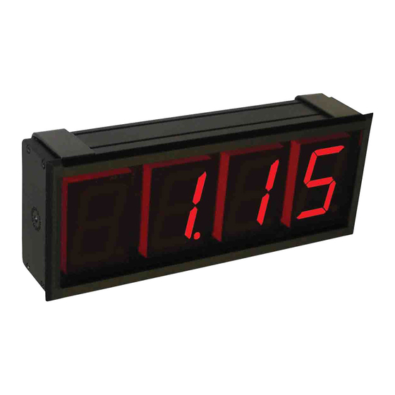
The Series DPMX Extra Large LED Digital Panel Meter can
easily be viewed from across a room or in dark areas. The 2.3"
LED segments are available in red, green, or blue. These panel
meters come equipped with a universal power supply and user
selectable process inputs to fit most applications. The Series
DPMX includes a mounting bracket that can be adjusted up to
180°.
INSTALLATION
The Series DPMX is designed to be bezel mounted or gimbal
mounted. Mounting brackets are included in the box.
BEZEL MOUNT
Remove the two U-brackets from the back of the panel meter.
Slide the unit through the panel from the front. Next, attach the U-
brackets to the rear and tighten the four retaining bolts.
See Figure 1 for dimensions of the cutout.
GIMBAL MOUNT
If the panel meter is to be gimbal mounted, remove and discard
the two U-brackets from the back of the panel meter. Fasten the
gimbal brackets to the mounting surface using appropriate
hardware. Lastly, fasten the panel meter loosely to the gimbals
using the thumbscrews. Note that detents are provided on both
sides of the case. Adjust the meter to the desired viewing angle
and securely tighten the thumb screws.
DWYER INSTRUMENTS, INC.
P.O. BOX 373 • MICHIGAN CITY, INDIANA 46361, U.S.A.
Series DPMX Extra Large Digital Panel Meter
Specifications - Installation and Operating Instructions
Figure 1
MINIMUM PANEL
CLAMP DIM.
(2-43/64)
(MAXIMUM PANEL
[67.87]
THICKNESS 1/2˝)
[12.70]
1-31/32
[50.04]
4-5/32
4[101.60]
[105.66]
29/32
[22.86]
SPECIFICATIONS
Inputs Ranges:
Set Voltage: ±200 mVDC, ±2 VDC, ±20 VDC.
Adjustable Voltage: 200 mVDC, 5 VDC, 10 VDC.
Adjustable Current: 0(4) to 20 mA DC.
Inputs Impedance: Set Voltage: >1 MΩ (>10 MΩ on 200 mV range).
Adjustable Voltage: 392 kΩ.
Adjustable Current: 300Ω nominal.
Accuracy: ±(1% F.S. + 1 count).
Power Supply: 90 to 250 VAC @12 VA or 10.5 to 30 VAC/DC @
6VA (depending on model).
Display: 3-1/2 digits, 2.3" height, 7 segment LED.
Sampling Rate: 3 readings per second.
Operating Temperature: -10 to 50ºC.
Storage Range: -40 to 75ºC.
Warm Up: 10 minutes.
Mounting: 180º gimbal mounting with 30º stops or bezel mount.
WIRING
The unit accepts signal inputs of 200 mVDC, 2 VDC, 5 VDC, 20
VDC, 10 VDC, and a 4 to 20 mA DC loop. The screw terminals for
wiring are located on the back of the adder board beneath the
cover. The cable clamps must be unfastened to access the screw
terminals. In order to reduce electrical noise, install the line voltage
and the process signal through separate cable clamps as shown
in Figure 2.
On the terminal cover, remove two thin break out sections that
best match the diameter of the wiring cables being used.
Phone: 219/879-8000
Fax: 219/872-9057
Bulletin G-62
10-19/32
[261.11]
10-19/32
[269.24]
REMOVABLE
COVER
Figure 2
www.dwyer-inst.com
e-mail: info@dwyer-inst.com
3-7/64
[78.99]
Advertisement
Table of Contents

Related Manuals for Dwyer Instruments DPMX Series


Summary of Contents for Dwyer Instruments DPMX Series
- Page 1 Figure 2 On the terminal cover, remove two thin break out sections that best match the diameter of the wiring cables being used. DWYER INSTRUMENTS, INC. Phone: 219/879-8000 www.dwyer-inst.com P.O. BOX 373 • MICHIGAN CITY, INDIANA 46361, U.S.A.
- Page 2 Three input positions are available for either VPI or DCV (see Figure 3 above). Move the switch to desired input range (see Figure 7). 200 mV RANGES 200 mV Figure 7 ©Copyright 2008 Dwyer Instruments, Inc. Printed in U.S.A. 11/08 FR# R5-443568-00 Rev. 2 DWYER INSTRUMENTS, INC. Phone: 219/879-8000 www.dwyer-inst.com P.O.
Need help?
Do you have a question about the DPMX Series and is the answer not in the manual?
Questions and answers