Sign In
Upload
Manuals
Brands
Olympus Manuals
Security Sensors
nortec 600
Olympus nortec 600 Manuals
Manuals and User Guides for Olympus nortec 600. We have
2
Olympus nortec 600 manuals available for free PDF download: User Manual, Getting Started Manual
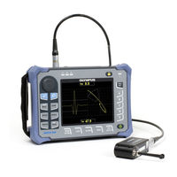
Olympus nortec 600 User Manual (374 pages)
Eddy current flaw detector
Brand:
Olympus
| Category:
Security Sensors
| Size: 10.24 MB
Table of Contents
Table of Contents
3
DMTA-10040-01EN, Rev. E, February
8
List of Abbreviations
9
Figure I-1 Label Attached to the Back of the Instrument
11
Labels and Symbols
11
Figure I-2 Location of the Serial Number
12
Table 1 Content of the Rating Label
12
Table 2 Content of the Probe Adaptor Labels
14
Important Information - Please Read before Use
17
Intended Use
17
Instruction Manual
17
Instrument Compatibility
18
Repair and Modification
19
Patent Rights Protection
19
Safety Symbols
20
Safety Signal Words
20
Note Signal Words
21
Safety
21
Warnings
22
Battery Precautions
23
Equipment Disposal
24
CE (European Community)
24
WEEE Directive
24
China Rohs
25
Korea Communications Commission (KCC)
26
EMC Directive Compliance
26
FCC (USA) Compliance
26
ICES-001 (Canada) Compliance
27
Warranty Information
27
Technical Support
28
Figure I-3 the NORTEC 600 Instrument
29
DMTA-10040-01EN, Rev. E, February
30
Introduction
29
1 Instrument Overview
31
Operating Principle
31
Contents of the Case
32
Connectors
33
Figure 1-1 Transport Case Contents
33
Figure 1-2 the NORTEC 600 Connections
34
Figure 1-3 the Top End Connectors
34
Figure 1-4 the Connectors Behind the Input/Output (I/O) Door
35
Power Requirements
36
Figure 1-5 the VGA out and I/O Connectors
36
Charger/Adaptor
37
Figure 1-6 Location of the NORTEC 600 Power Button and Indicator Light
37
Figure 1-7 the Charger/Adaptor Indicator Light on the Front Panel
37
Figure 1-8 Connecting the Charger/Adaptor
38
Figure 1-9 Connecting the DC Power Cable
39
Table 3 Charger/Adaptor and Battery Indicators
39
Battery Compartment
40
Figure 1-10 the Battery Compartment
40
Lithium-Ion Battery
41
Alkaline Batteries
42
Figure 1-11 Removing the Lithium-Ion Battery
42
Optional Microsd Card Installation
43
Figure 1-12 the Alkaline Battery Holder
43
NORTEC 600 Hardware Features
44
Figure 1-13 Installing the Microsd Card
44
Figure 1-14 Overview of the NORTEC 600 Hardware - Front View
45
Hardware Overview
45
Figure 1-15 Overview of the NORTEC 600 Hardware - Back View
46
Front Panel and Smartknob
46
Figure 1-16 the NORTEC 600 Front Panel with Smartknob and Keypad
47
Keypad
47
Figure 1-17 the NORTEC 600 English Keypad
48
Figure 1-18 the NORTEC 600 Chinese Keypad
48
Figure 1-19 the NORTEC 600 Japanese Keypad
49
Figure 1-20 the NORTEC 600 International Keypad
49
Table 4 Keypad Functions
50
Connectors
52
Figure 1-21 Location of the PROBE (LEMO) and BNC Connectors
52
Input/Output (I/O) and VGA out Connectors
52
Probe and BNC Connectors
52
Figure 1-22 the VGA out and I/O Connectors
53
Figure 1-23 the Microsd Slot and USB Port
54
Microsd and USB Port
54
Figure 1-24 Instrument Stand
55
Instrument Stand
55
Various Hardware Features
55
Display Protection
56
Environmental Ratings
56
O-Ring Gasket and Membrane Seals
56
2 Software User Interface
59
Starting up the Instrument
59
Figure 2-1 the Instrument Label Showing Keypad Functions
59
Figure 2-2 Application Choices on the Quick-Setup Menu
60
Navigating the Application Menu
60
Figure 2-3 the Powerlink Recognition Screen
61
Main Inspection Screen
61
Figure 2-4 the Main Inspection Screen
62
Figure 2-5 the NORTEC 600 Front Panel and Main Inspection Screen
63
Selecting from the Menus
64
Displaying All Functions Simultaneously - ALL SETTINGS Menu
64
Figure 2-6 the ALL SETTINGS Menu
65
Using the ALL SETTINGS Menu
65
Special Functions in the ALL SETTINGS Menu
66
Displaying Real-Time Readings
66
Figure 2-7 Example of VPP and DEG PP
67
Figure 2-8 Example of HPP
67
Figure 2-9 Example of VPP
68
Figure 2-10 Example of HMAX
68
Enabling Real-Time Readings on the Main Inspection Screen
69
Figure 2-11 Example of VMAX
69
Enabling the Real-Time Readings in Full-Screen Mode - FULL NEXT Key
70
3 Initial Setup
73
Setting the User Interface Language and the Decimal Symbol
73
Figure 3-1 the SYSTEM SETUP Screen
73
Setting the Clock
74
Changing the Location of Saved Files
74
Changing the Display Settings
75
DMTA-10040-01EN, Rev. E, February
75
Changing the Display Brightness
76
Adjusting Auto Erase
77
Selecting the Startup Screen
77
Enabling Knobless Entry for Harsh Environments
78
4 Control Functions
79
Powerlink
79
Figure 4-1 the Powerlink Recognition Screen
79
Instrument Controls
80
Figure 4-2 the NORTEC 600 Instrument Controls
80
Direct-Function Keys
81
Display
81
Power and Lock Buttons
81
Figure 4-3 Probe Liftoff-Initially Not Horizontal
83
Figure 4-4 the LIFT PROBE Message after Holding the A-LIFT NULL Key
83
Figure 4-5 Probe Liftoff after Nulling
84
Figure 4-6 Freezing the Current Image on the Instrument Screen
85
Menu Keys
87
Figure 4-7 the up and down Function in Knobless Entry
88
Hidden Function - Screen Capture
88
Knob
88
Knobless Entry
88
Ambidextrous Controls
89
Figure 4-8 the SYSTEM SETUP Screen
90
Figure 4-9 the Controls Displayed on the Right Side of the Instrument
90
FULL NEXT Key
90
Figure 4-10 the Settings Display (Left) and Maximized Display (Right)
91
Figure 4-11 Using the FULL NEXT Key to Navigate a Menu
91
Menus
92
Frequency (FREQ 1) Menu - MAIN FILTER Key
92
Filter Menu - MAIN FILTER Key
94
Special Menu - MAIN FILTER Key
95
Display Menu - DISP Key
97
Figure 4-12 the EDDY CURRENT SLIDE RULE Menu
97
Alarm Menu - ALARM Key
101
Memory Menu - MEM Key
102
Figure 4-13 the SHOW READINGS Function
103
Figure 4-14 the HIDE READINGS Function
103
Figure 4-15 the STORE Function
105
Memory Text Editor
106
Figure 4-16 the FILE MANAGER Menu's Memory Text Editor and Special Buttons
107
Advanced Setup Menu - ADV SETUP Menu Key
109
Figure 4-17 the Application Selection Menu
110
Figure 4-18 the ALL SETTINGS Menu (First of Two Screens)
111
Figure 4-19 the FREQ 1 Menu
112
Figure 4-20 the FREQ 2 Menu
113
Figure 4-21 the PASSWORD Menu
114
Figure 4-22 the SYSTEM SETUP Screen
115
Figure 4-23 the about Menu
116
Figure 4-24 the REGULATORY SCREEN
117
Dual Frequency Menus
119
Figure 4-25 the RESET Menu
119
Frequency (FREQ 1) Menu - MAIN FILTER Key
119
Table 5 Reset Types
119
Frequency (FREQ 2) Menu - MAIN FILTER Key
121
MIX Menu in Dual Frequency - MAIN FILTER Key
123
Filter Menu in Dual Frequency - MAIN FILTER Key
124
Special Menu in Dual Frequency - MAIN FILTER Key
124
Display Menu in Dual Frequency - DISP Key
126
ALARM Menu in Dual Frequency - ALARM Key
128
5 Using the Instrument
129
Common NORTEC 600 Applications
130
Detecting Surface-Breaking Cracks - General Purpose Procedure for All NORTEC 600 Models
130
Figure 5-1 Materials-Surface-Breaking Cracks
130
Figure 5-2 the Surface Cracks Application
131
Figure 5-3 the Automatic Lift-Off Function
133
Figure 5-4 the Lift-Off Signal as Close as Possible to Horizontal
133
Figure 5-5 Adjusting the Horizontal Gain
134
Figure 5-6 Adjusting the Vertical Gain
134
Figure 5-7 the Final Calibration Check
135
Inspecting Fastener Holes with a Rotating Scanner - NORTEC 600S and NORTEC 600D Models
136
Figure 5-8 the Full-Screen Mode for Fine-Tuning the Settings
136
Figure 5-9 the List of All Parameters
136
Figure 5-10 Materials-Fastener Holes with Rotating Scanner
137
Figure 5-11 the Bolt Hole Application
138
Figure 5-12 the Bolt-Hole Signal
139
Figure 5-13 Adjusting the Lift-Off Noise (First Alternative)
139
Figure 5-14 Adjusting the Lift-Off Noise (Second Alternative)
140
Figure 5-15 Adjusting the Gain
141
Figure 5-16 Adjusting the Vertical Gain
141
Figure 5-17 the Full-Screen Mode for Fine-Tuning the Settings
142
Figure 5-18 the List of All Parameters for Aluminum
143
Figure 5-19 an Example Display for a Steel Hole
144
Figure 5-20 the List of All Parameters in Ferromagnetic Material
144
Detecting Sub-Surface Cracks at very Low Frequency - All NORTEC 600 Models
145
Figure 5-21 Comparing the Figure 6 (Left) and Figure 8 Filter Signals
145
Figure 5-22 Materials-Sub-Surface Cracks at very Low Frequency
146
Figure 5-23 the Sub-Surface Application
147
Figure 5-24 the Signal on the Cracked Fastener
148
Figure 5-25 the Lower Lift-Off Signal as Close as Possible to Horizontal
148
Figure 5-26 Adjusting the Vertical Gain
149
Figure 5-27 the Signal in Full-Screen Mode
149
Figure 5-28 the List of All Parameters
150
Inspecting Welds on Ferromagnetic Materials - All NORTEC 600
151
Figure 5-29 Calibration with Frequency too Low (Left) or too High (Right)
151
Figure 5-30 Materials-Welds on Ferromagnetic Material
151
Models
151
Figure 5-31 the Weld and Wheel Application
152
Figure 5-32 the Longest Face of the Probe Tip
153
Figure 5-33 the Signal on the Notch
153
Figure 5-34 the Notch Signal Oriented Vertically
154
Figure 5-35 Adjusting the Vertical Gain
154
Figure 5-36 the Signal after Scanning the Entire Standard
155
Figure 5-37 the Default Display of Maximum Signal Amplitude and Signal Angle
156
Figure 5-38 the Scanning Motions
157
Evaluating Paint Thickness on Ferromagnetic Material - All NORTEC 600 Models
158
Figure 5-39 the List of All Parameters
158
Figure 5-40 Materials-Paint Thickness on Ferromagnetic Material
159
Figure 5-41 the Surface Cracks Application
160
Figure 5-42 Decreasing the GAIN to Adjust the Signal
161
Figure 5-43 Adjusting V POS to Create a Vertical Mark
161
Figure 5-44 the Vertical Lines for Different Thicknesses
162
Figure 5-45 Using the Vertical Reference Marks for Thickness Evaluation
163
Figure 5-46 the List of All Parameters
163
Measuring Conductivity and Nonconductive Coating Thickness - NORTEC 600C, NORTEC 600S, and NORTEC 600D Models
164
Figure 5-47 Materials-Conductivity and Non-Conductive Coating Thickness
164
Figure 5-48 Accessing the Conductivity Function
165
Figure 5-49 the Displayed Instruction (1) after Powerlink Acceptance
165
Figure 5-50 the Displayed Instruction (3)
166
Figure 5-51 the Displayed Instruction (4)
167
Figure 5-52 the Confirmation of a Completed Calibration
167
Inspecting Aircraft Wheels - All NORTEC 600 Models
170
Figure 5-53 Materials-Aircraft Wheels
170
Figure 5-54 the Surface Cracks Application
171
Figure 5-55 the Signals Extending Across the Screen
172
Figure 5-56 Scanning the Center Notch
172
Figure 5-57 Setting the Signal as Close as Possible to Horizontal
173
Figure 5-58 the Signals Extending Vertically Across the Screen
173
Figure 5-59 the Results after Scanning the Standard
174
Figure 5-60 the Alarm Parameters
175
Inspecting Critical Fastener Holes with a Controlled Translation (Indexing) Scanner - NORTEC 600S and NORTEC 600D Models
176
Figure 5-61 the Signal after Fine Tuning
176
Figure 5-62 the List of All Parameters
176
Figure 5-63 the Indexing Scanner Application
177
Figure 5-64 the Figure 6 Filter
178
Figure 5-65 Adjusting the Signal Angle
179
Figure 5-66 Adjusting the Gain
179
Figure 5-67 Adjusting the Vertical Gain
180
Figure 5-68 Adjusting the Sync Angle
180
Figure 5-69 Using the Waterfall Cursor
182
Figure 5-70 the Scan Result
182
Special and Educational Applications
183
Figure 5-71 the List of All Parameters
183
Figure 5-72 Materials-Special and Educational Applications
184
Models
184
Using the Impedance Plane Theory and Display - All NORTEC 600
184
Figure 5-73 the Surface Cracks Application
185
Figure 5-74 the Section of the Standard Used for Impedance Plane Theory
186
Figure 5-75 Adjusting the Signal Angle to 90
186
Figure 5-76 Adjusting the Gain
187
Figure 5-77 Displaying the Effect of Conductivity and Magnetic Permeability
187
Sorting Metals by Evaluating Conductivity - All NORTEC 600 Models
187
Figure 5-78 the Surface Cracks Application
188
Figure 5-79 the Section of the Standard Used for Conductivity Evaluation
189
Figure 5-80 the Signals from Different Conductivity Samples
189
Figure 5-81 Adjusting the Lower Signal to Horizontal
190
Figure 5-82 Adjusting the Vertical Gain
190
Evaluating Nonconductive Coating (Paint) Thickness - All NORTEC 600 Models
191
Figure 5-83 Using the Vertical Position of the Signal to Accept or Reject the Sample
191
Figure 5-84 the Surface Cracks Application
192
Figure 5-85 the Back of the Standard
192
Figure 5-86 Adjusting the Lift-Off Angle to 90
193
Figure 5-87 Adjusting the Gain
193
Figure 5-88 Using H POS to Create a Horizontal Mark
194
Figure 5-89 Creating more Horizontal Marks
194
Evaluating Metal Thickness and Using Thickness Curve Theory - All NORTEC 600 Models
195
Figure 5-90 Using the Vertical Signal Deflection to Evaluate Unknown Thicknesses
195
Figure 5-91 the Surface Cracks Application
196
Figure 5-92 the Section of the Standard Used for Metal Thickness
196
Figure 5-93 the Scan of the Tapered Area
197
Figure 5-94 Adjusting the Lift-Off Angle to Horizontal
198
Figure 5-95 Adjusting the Gain
198
Advanced Dual Frequency Applications
199
Figure 5-96 the Scan of the Tapered Part
199
Detecting Corrosion Using Dual Frequency to Reduce the Pillowing Effect - NORTEC 600D Model
200
Figure 5-97 Materials-Dual Frequency for Corrosion
200
Figure 5-98 the Dual Frequency Sub-Surface Application
201
Figure 5-99 the List of Dual Frequency Parameters
202
Figure 5-100 Position 1 of the Standard
203
Figure 5-101 Adjusting the Angle of the Frequency 1 Lift-Off Signal
203
Figure 5-102 Adjusting the Angle of the Frequency 2 Lift-Off Signal
204
Figure 5-103 Position 2 on the Standard
204
Figure 5-104 the Frozen Signals
205
Figure 5-105 Adjusting the Gain for Frequency 1
205
Figure 5-106 Adjusting the Gain for Frequency 2
206
Figure 5-107 Adjusting the H GAIN for Frequency 1
207
Figure 5-108 Adjusting the H GAIN 2 Value
207
Figure 5-109 Adjusting the H GAIN Value
208
Figure 5-110 Adjusting the H MIX GN Value
209
Figure 5-111 Adjusting the V MIX GN Value
209
Figure 5-112 the Corrosion-Defect Scan Result
210
Detecting Sub-Surface Cracks Using Dual Frequency in a Lap Splice with Anodized and Alodine Rivets - NORTEC 600D Model
211
Figure 5-113 the List of All Parameters
211
Figure 5-114 Materials-Dual Frequency for Sub-Surface Cracks
212
Figure 5-115 the Dual Frequency Sub-Surface Application
213
Figure 5-116 the List of Dual Frequency Parameters
214
Figure 5-117 Position 1 on the Standard
215
Figure 5-118 Adjusting the ANGLE Value
215
Figure 5-119 Adjusting the ANGLE 2 Value
216
Figure 5-120 Adjusting the Amplitude of the Frequency 1 Signal
216
Figure 5-121 Adjusting the Amplitude of the Frequency 2 Signal
217
Figure 5-122 the Fastener Scan Result
218
Figure 5-123 Adjusting the Horizontal Amplitude of the Frequency 1 Signal
218
Figure 5-124 Adjusting the Vertical Amplitude of the Frequency 1 Signal
219
Figure 5-125 Adjusting the Horizontal Amplitude of the Frequency 2 Signal
219
Figure 5-126 Adjusting the Vertical Amplitude of the Frequency 2 Signal
220
Figure 5-127 Position 3 on the Standard
221
Figure 5-128 Adjusting the V GAIN 2 Value
221
Figure 5-129 Adjusting the V GAIN Value
222
Figure 5-130 Checking the MIX Signal
222
Figure 5-131 Adjusting the ANGLE Value
223
Figure 5-132 Adjusting the H GAIN 2 Value
223
Figure 5-133 the Scan Results for both Fastener Rows
224
Figure 5-134 the List of All Parameters
225
Inspecting Heat Exchanger Tubing Using Dual Frequency - NORTEC 600D Model
225
Figure 5-135 Materials-Dual Frequency for Heat Exchanger Tubing
226
Figure 5-136 the Heat Exchanger Tubing Application
227
Figure 5-137 the Scan of the Thru-Wall Hole
228
Figure 5-138 Adjusting the Frequency 1 Signal Phase
229
Figure 5-139 Adjusting the Frequency 1 Gain
229
Figure 5-140 Adjusting the Frequency 2 Angle
230
Figure 5-141 the Scan of the Support Ring
230
Figure 5-142 Adjusting the Angle of the Frequency 2 Signal on the Support Ring
231
Figure 5-143 Adjusting the Gain of the Frequency 2 Signal on the Support Ring
231
Figure 5-144 the Support Ring Scan with AUTO MIX
232
Figure 5-145 the Support Ring's Signal Successfully Subtracted
233
Figure 5-146 the Scan of the Thru-Wall Hole
233
Figure 5-147 Fine-Tuning the MIX Angle
234
Figure 5-148 the Scan of the Flat-Bottom Holes
234
Figure 5-149 the List of All Parameters
235
Figure 5-150 the Strip Chart Display
236
Figure 5-151 the Web Grid Display
237
Heat Exchanger Tubing Applications
238
Figure 5-152 the Display with Adjusted Null Point and Coarse Grid
238
Table 6 Recommendations for Heat Exchanger Tubing Applications
239
ECT Pitting, Wear, and Cracks - NORTEC 600D Model
240
Figure 5-153 an Example of Marking the Probe Positions
240
Figure 5-154 ECT Principles
241
Figure 5-155 an Example of an ECT Differential Signal Response
242
Figure 5-156 an Air Conditioner Probe
242
Figure 5-157 Signals from an A/C Probe's Pancake Surface Coils Only
243
Using the Application
243
Figure 5-158 the ECT Pitting, Wear, and Cracks Application
244
Figure 5-159 Example of Lower Signal Lobe When Pulling the Probe over a Flaw
245
Figure 5-160 the Scan Signal of the Thru-Wall Hole
245
Figure 5-161 Adjusting the Signal
246
Figure 5-162 Adjusting the Frequency 1 Gain
246
Figure 5-163 an Example of a Nonsaturated Support Ring Signal
247
Figure 5-164 an Example of a Saturated Support Ring Signal
248
Figure 5-165 the Tube Scan between the Support Ring and the Thru-Wall Hole
248
Figure 5-166 the Verified Signals: Thru-Wall Hole (Left) and Support Ring (Right)
249
Figure 5-167 the Frequency 2 Scan Signal of the Support Ring
250
Figure 5-168 the Frequency 2 Scan Signal of the 1.3 MM (0.052 In.) Thru-Wall Hole
250
Figure 5-169 the Frequency 2 Scan Signal of the 1.3 MM (0.052 In.) Thru-Wall Hole with Adjusted Angle
251
Figure 5-170 the Support Ring Signal after AUTO MIX
252
Figure 5-171 the Thru-Wall Hole Signal after AUTO MIX
253
Figure 5-172 the Thru-Wall Hole Signal after AUTO MIX Angle Adjustment
253
Figure 5-173 the Thru-Wall Hole Signal after AUTO MIX Gain Adjustment
254
Figure 5-174 the Tube Scan Result
255
Figure 5-175 Moving the Support Ring
256
Figure 5-176 the Null Position after Moving the Support Ring
256
Figure 5-177 the Tube Scan Result after Moving the Support Ring (MIX)
257
Figure 5-178 the Scan Result with the Support Ring over the Flaw in FREQ 1
257
Displaying Reference Signals
258
Figure 5-179 Tube Scan Display with Reference Image (Gray) and Live Signal (Orange)
259
Using the ALL-IN-1 (Strip Chart) Display
259
Figure 5-180 the FRQ2 DSP Menu
260
Figure 5-181 the Tube Scan with the ALL-IN-1 Display
260
ECT Erosion and Corrosion - NORTEC 600D Model
261
Figure 5-182 an Example of an ECT Absolute Signal Response
261
Figure 5-183 the ECT Erosion and Corrosion Application
262
Figure 5-184 the Scan of the Two Grooves
263
Figure 5-185 Adjusting the Signal Phase
263
Figure 5-186 Adjusting the Gain
264
Figure 5-187 the 10 % ID and 20 % OD Flaws Set as a Reference Image
265
Figure 5-188 the Tube Scan Result
265
RFT Pitting and Wear - NORTEC 600D Model
266
Figure 5-189 an RFT Probe
267
Figure 5-190 an Example of an RFT Differential Signal Response
267
Figure 5-191 a Dual Exciter Probe
268
Figure 5-192 Equal Response on both Sides of a Support with a Dual Exciter Probe
268
Figure 5-193 the RFT Pitting and Wear Application
269
Using the Application
269
Figure 5-194 the Scan of the Thru-Wall Hole
270
Figure 5-195 Adjusting the Signal Phase
271
Figure 5-196 Adjusting the Gain
271
Figure 5-197 a Slow Scan Rate (Optimal Signal, Left) and a Fast Scan Rate (Loss of Signal, Right)
272
Figure 5-198 the Support Ring's Signal Clipped (Left) and with Adjusted Gain (Right)
273
Figure 5-199 the Scan of the Entire Length of the Tube
274
Figure 5-200 Angle Adjustment in FREQ 2
274
Figure 5-201 GAIN Adjustment in FREQ 2
275
Figure 5-202 Verification Signal in FREQ 2
275
Figure 5-203 the MIX Menu
276
Figure 5-204 the Scan of Entire Tube Length after AUTO MIX
277
Enhancing the Signal with the lo PASS Filter
278
Figure 5-205 the Signal after AUTO MIX (Left); with Angle/Gain Adjustment (Right)
278
Figure 5-206 a Scan with 10 Hz lo PASS Filter (Left); with Scan Rate too Fast (Right)
279
Using the ALL-IN-1 Display
279
Figure 5-207 ALL-IN-1 Display of Cluster of 4 Corrosion Pits under Support Ring
280
Figure 5-208 ALL-IN-1 Display with Support Ring Within 3.2 MM (0.125 In.) of 75 % Corrosion Pit
281
Figure 5-209 an Example of an RFT Absolute Signal Response
281
RFT Erosion and Corrosion - NORTEC 600D Model
281
Figure 5-210 a Single Exciter Probe
282
Figure 5-211 a Large Defect Detected on both Sides of a Support Using the Absolute (ABS) Channel
282
Using the Application
282
Figure 5-212 the RFT Erosion and Corrosion Application
283
Figure 5-213 the Scan of the Two Grooves
284
Figure 5-214 Adjusting the Signal Phase
284
Figure 5-215 Adjusting the Gain and Angle
285
Figure 5-216 the 40 % OD and 60 % OD Flaws Set as a Reference Image
286
Figure 5-217 the Scan of the Entire Length of the Tube
286
Figure 5-218 Renaming the File
287
Using the Overlay Display
287
DMTA-10040-01EN, Rev. E, February
288
Figure 5-219 the Overlay (Background Voltage Plane for Absolute RFT Signal Analysis) and the Scan of the Tube
288
Optimizing the Frequency
288
Figure 5-220 the Readings for 40 % OD Loss (Left) and 60 % OD Loss (Right)
289
Figure 5-221 a Finned Air-Cooler Tube (Fin-Fan)
289
NFT Pitting (Differential) - NORTEC 600D Model
289
Figure 5-222 the NFT Inspection Technology
290
Figure 5-223 the Differential Exciter-Pickup Configuration
290
Figure 5-224 Example NFT Signal Responses (Differential Configuration)
291
Figure 5-225 the NFT Pitting Application
292
Figure 5-226 Example of Lower Signal Lobe When Pulling the Probe over a Flaw
293
Figure 5-227 the Scan Signal of the Thru-Wall Hole
293
Figure 5-228 Adjusting the Signal Phase
294
Figure 5-229 Adjusting the Gain
294
Figure 5-230 the SWP + IMP Display
295
Figure 5-231 the SWP + IMP Display after Inspecting the Entire Tube
296
Figure 5-232 an NFT Probe with an Absolute Exciter-Pickup Configuration
296
NFT Erosion and Corrosion (Absolute) - NORTEC 600D Model
296
Figure 5-233 Example Signal Response (NFT Absolute Configuration)
297
Figure 5-234 the NFT Erosion and Corrosion Application
298
Figure 5-235 the Scan Signal of the 60 % Wall-Loss Groove
299
Figure 5-236 Adjusting the Signal Phase
299
Figure 5-237 Adjusting the Gain
300
Figure 5-238 the 40 % Wall-Loss Groove (Left) and 60 % Wall-Loss Groove (Right)
301
Alarm DEFINE Menu
302
Alarm Menus
302
Figure 5-239 the SWP + IMP Display after Inspecting the Entire Tube
302
Figure 5-240 Alarm DEFINE Menu
303
Figure 5-241 Alarm Polarity
304
Selecting the Alarm Shape and Position - Alarm 1, 2, and 3 Menus
304
Figure 5-242 Alarm Menu
305
SWEEP Alarm
305
Figure 5-243 Alarm Polarity
306
6 NORTEC PC Software
307
Importing Files
307
Figure 6-1 the Import File Wizard Dialog Box
308
Figure 6-2 the Import File Wizard Folder Selection
308
Figure 6-3 the Import File Wizard File Selection
309
Figure 6-4 the Import File Wizard Transfer Process Start
309
Capturing a Screen Image Using NORTEC PC
310
Figure 6-5 the Import File Wizard Transfer Process Completion
310
Figure 6-6 the NORTEC PC Device Menu
311
Figure 6-7 the Capture Screen Dialog Box
311
Upgrading the Instrument Software Using NORTEC PC
312
Figure 6-8 the about Menu
312
Figure 6-9 the UPGRADE Menu
313
Figure 6-10 the Message Indicating the Charger/Adaptor Is Not Connected
313
Figure 6-11 the Message Indicating the Charger/Adaptor Is Connected
314
Figure 6-12 the Utilities Menu
314
Upgrading the Instrument Software Without NORTEC PC
315
Figure 6-13 the Upgrade Device Dialog Box
315
Creating a PDF
317
Figure 6-14 Files in the Left Pane of the NORTEC PC Window
317
Issuing Remote Commands to the NORTEC 600 from a PC
318
Figure 6-15 the File Menu
318
Figure 6-16 Selecting the Remote Command
318
Figure 6-17 the Device Menu - Issue Command
319
Figure 6-18 the Issue Command Dialog Box
319
Table 7 NORTEC 600 Remote Commands
321
Remotely Controlling the NORTEC 600 from a PC
328
Figure 6-19 the Remote Command Dialog Box
329
Managing Files on the NORTEC 600 from Your PC
330
Figure 6-20 the Knob Functions in Remote Control Operation
330
Figure 6-21 the File Manager Command
330
Figure 6-22 the Manage File Dialog Box
331
Figure 6-23 the Confirmation Dialog Box for File Deletion
332
Figure 6-24 the Rename Dialog Box
332
Unlocking NORTEC 600 Upgrade Options with Your PC
333
Figure 6-25 Message Asking You to Confirm the Recall
333
Figure 6-26 the Unlock Options Command
334
Figure 6-27 the Unlock Options Dialog Box
334
6.10 Backing up the NORTEC 600 Files
335
Figure 6-28 the Microsd Card Location
335
Figure 6-29 the Backup Command
336
Figure 6-30 the Backup Dialog Box (Start)
336
Figure 6-31 the Confirmation Dialog Box to Confirm Backup Start
336
6.11 Restoring or Cloning the NORTEC 600 Files
337
Figure 6-32 the Backup Dialog Box (Complete)
337
Figure 6-33 the Restore Command
337
Figure 6-34 the Restore Dialog Box (Start)
338
Figure 6-35 the Confirmation Dialog Box to Confirm the Restore Start
338
Figure 6-36 the Restore Dialog Box (Complete)
338
7 Maintenance and Troubleshooting
339
Lithium-Ion Battery
339
Error Messages
340
Probe Care and Diagnostics
341
Appendix A: Specifications
343
General and Environmental Specifications
343
Table 8 General and Environmental Specifications
343
Input/Output Specifications
348
Figure A-1 Pin Numbers on Connectors
349
Table 9 NORTEC 600 Input/Output 15-Pin I/O Connector
350
Table 10 NORTEC 600 VGA 15-Pin Port Output
350
Appendix B: Accessories, Replacement Parts, and Upgrades
351
Table 11 Standard Accessories and Replacement Parts
351
Table 12 Optional Accessories and Support Items
352
Table 13 NORTEC 600 Instrument Upgrades
352
Table 14 Power Cords for Charger EP-MCA-X and EPXT-EC-X
353
Table 15 Conductivity Accessories (for N600C Model Only)
353
Table 16 Adaptor Cables for Scanners from Other Manufacturers
353
Table 17 Getting Started Guide - All Languages
354
Table 18 Heat Exchanger Tubing Accessories - for N600D Model Only
354
List of Figures
357
List of Tables
367
Index
369
Advertisement
Olympus nortec 600 Getting Started Manual (12 pages)
Eddy Current Flaw Detector
Brand:
Olympus
| Category:
Security Sensors
| Size: 1 MB
Table of Contents
Contents of the Case
2
Charging the Lithium-Ion Battery
3
Starting up the Instrument
5
Navigating the Application Menu
5
Main Inspection Screen
6
Battery Precautions
11
Equipment Disposal
11
Advertisement
Related Products
Olympus NEWPIC Zoom 90
Olympus NOTE CORDER DP-311
Olympus EPOCH 1000 Series
Olympus EPOCH 600
Olympus EPOCH 6LT
Olympus Panametrics Epoch 4 Plus
Olympus Sonic 1200S/HR
Olympus Categories
Digital Camera
Voice Recorder
Microscope
Camera Accessories
Camera Lens
More Olympus Manuals
Login
Sign In
OR
Sign in with Facebook
Sign in with Google
Upload manual
Upload from disk
Upload from URL